NOTE: This tutorial was updated on 08/2016 to match the updated version of the platform
If you would like to watch the first session of the Drone Workshop again or in the case you missed it, you can access the full recording below.
 - Aerodynamics of a Single Rotating Propeller")
In this homework assignment we will review the lessons from the first session of our online Drone Workshop. You will learn how to set up a simulation of the aerodynamics of a drone.
Level 1
Background:
The aim of the first part of this homework assignment is to investigate and compare the aerodynamic characteristics of two different quadcopter propeller designs.
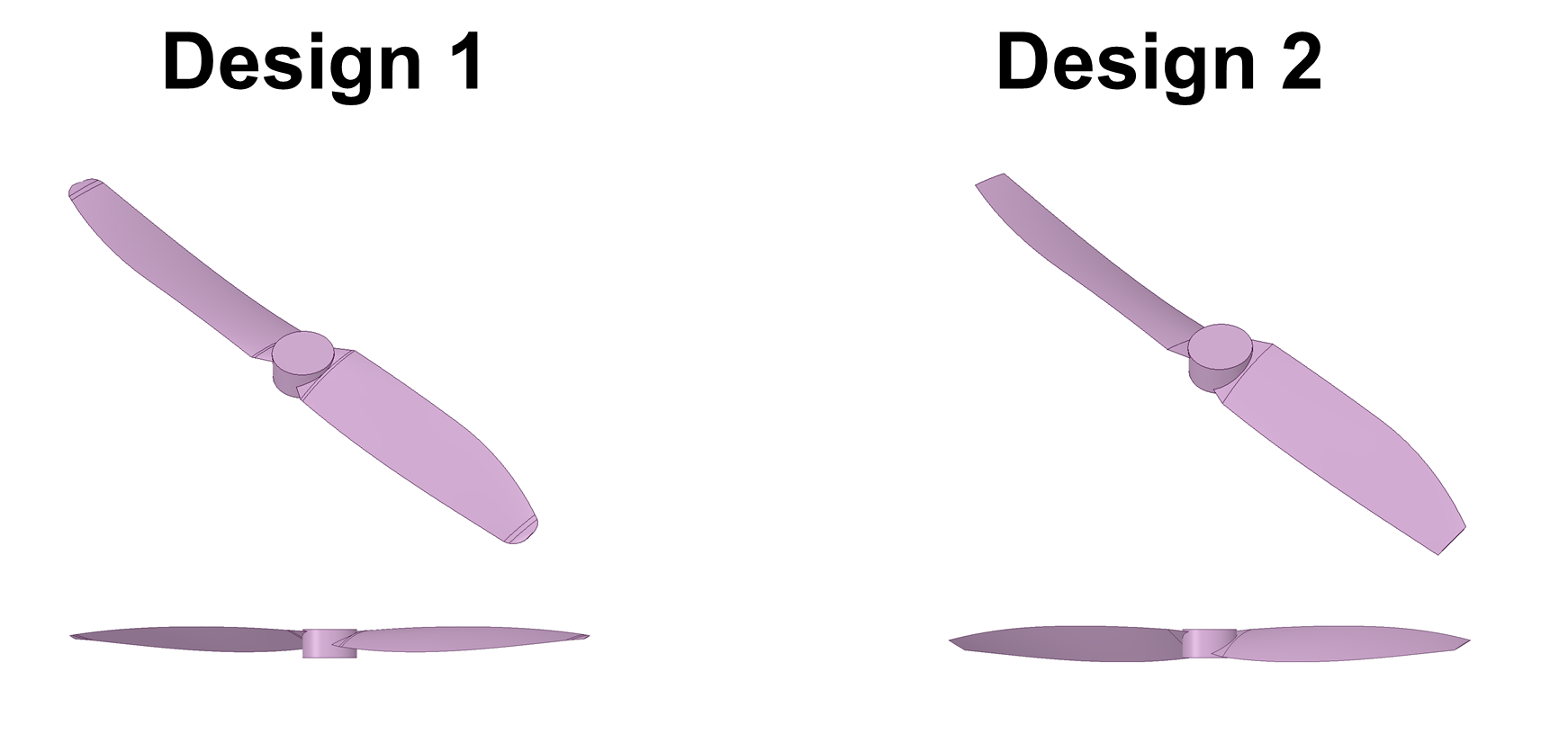
We will analyze the lift generated by the propeller depending on the rotational speed for each propeller design at a rotational speed of 525,1050, 1575 and 2100 rad/s
Your final homework project should contain 8 simulations (4 for every mesh).
Exercise:
You should set up a flow simulation based on a provided mesh. Thus, you only have to define the boundary conditions and some numerical settings.
Let’s take a look at the physics of the drone before we start to set up our simulations:
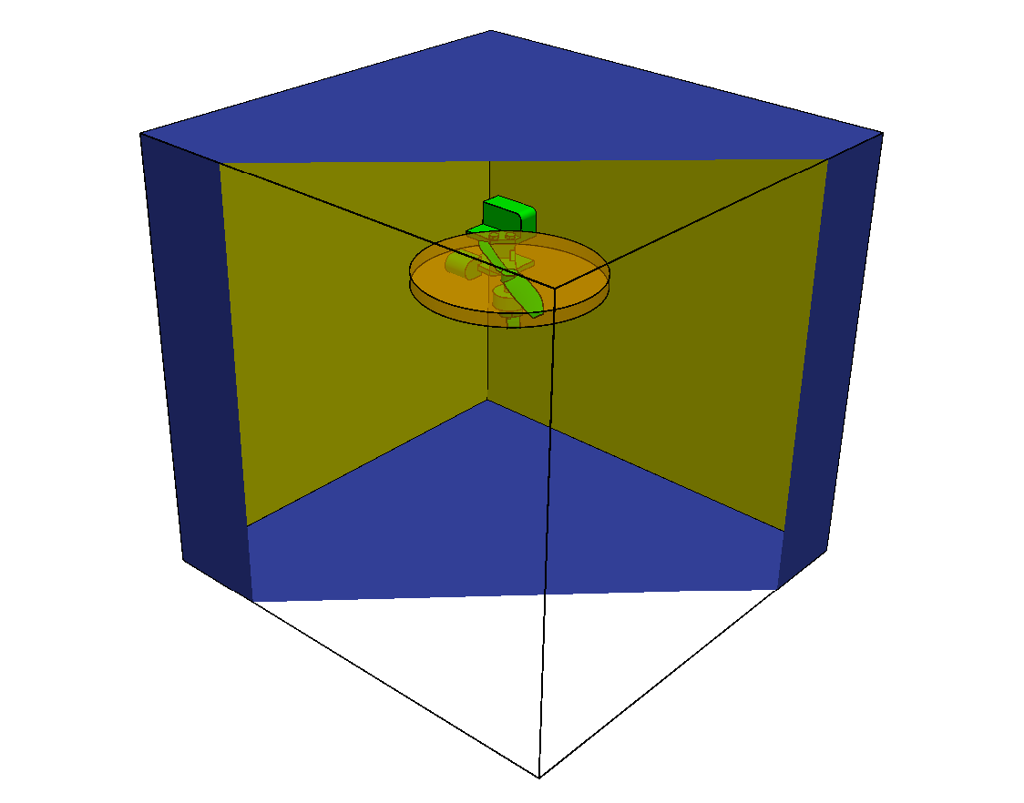
The first thing you will notice about the mesh of the drone is the fact that it only contains a quarter of the actual geometry. This is because the drone is a symmetric body. Thus it is best to simulate only one quarter of the drone to reduce the computational effort by defining the inner surrounding walls (yellow) as symmetry planes.
The outer, lower and upper surrounding walls (blue) are necessary to limit the domain we want to simulate, since we are not able to simulate an infinitely large domain. Nevertheless they do not exist in reality and should therefore not interact with the flow. A good approximation here is to assume this wall is frictionless (slip walls).
The body of the drone is a physical wall (green), which means that it involves friction. This faces (including the propeller) should be considered as non-slip walls.
To include the effect of the rotating propeller to the simulation we will use a technology called MRF (Multiple Reference Frame). Instead of “moving” the mesh which would create a high computational effort, the MRF approach allows to add the rotation of the air around the propeller (orange) directly.
Step-by-Step instruction
Note: These instructions refer to the simulation setup of the first propeller design. The setup for the second design alternative is the same and will therefore not be covered.
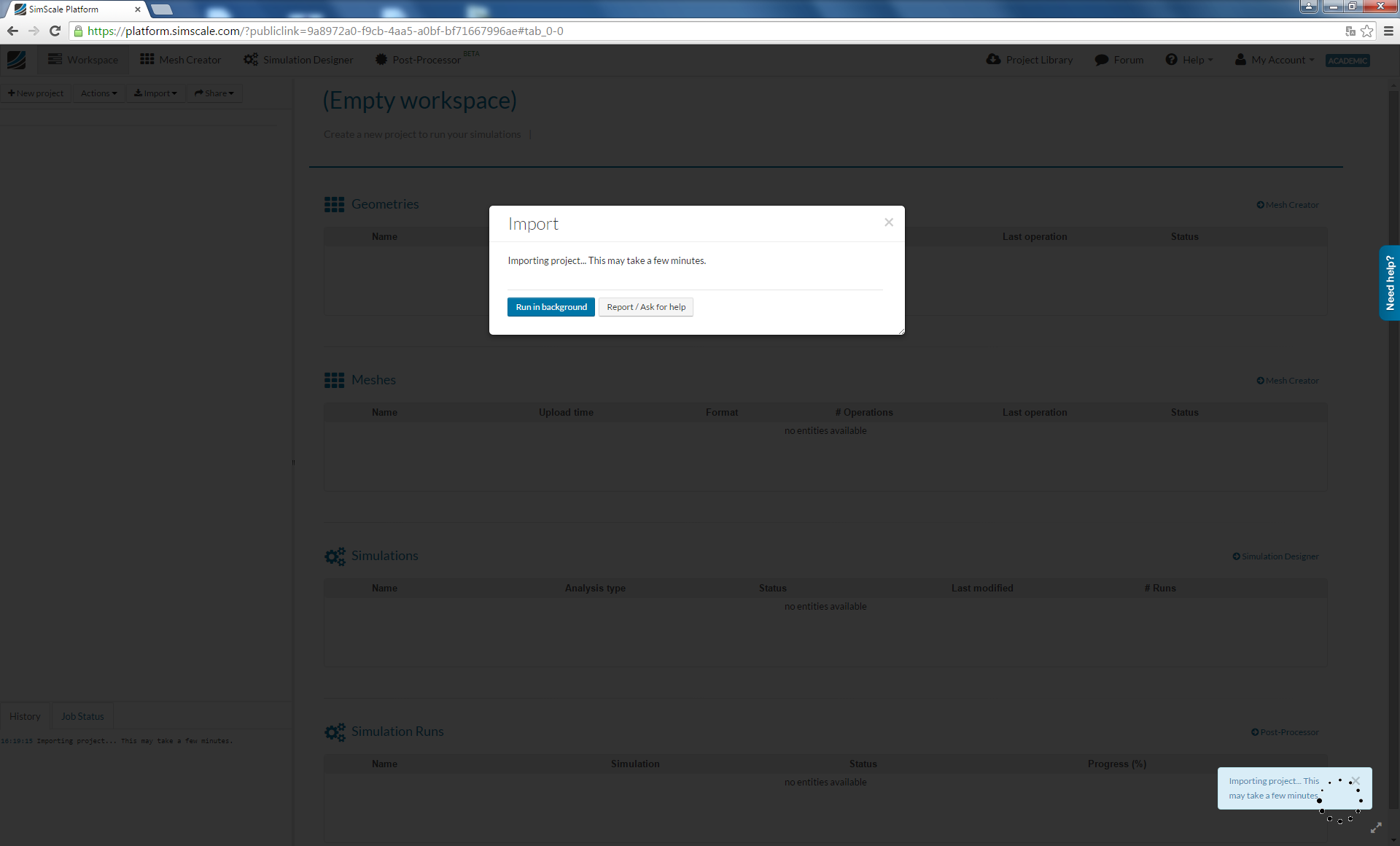
First you need to import the mesh into your SimScale workspace. For this, you only have to click on this link
and a project with everything you need will be added to your workspace. Please note that this can take several minutes.
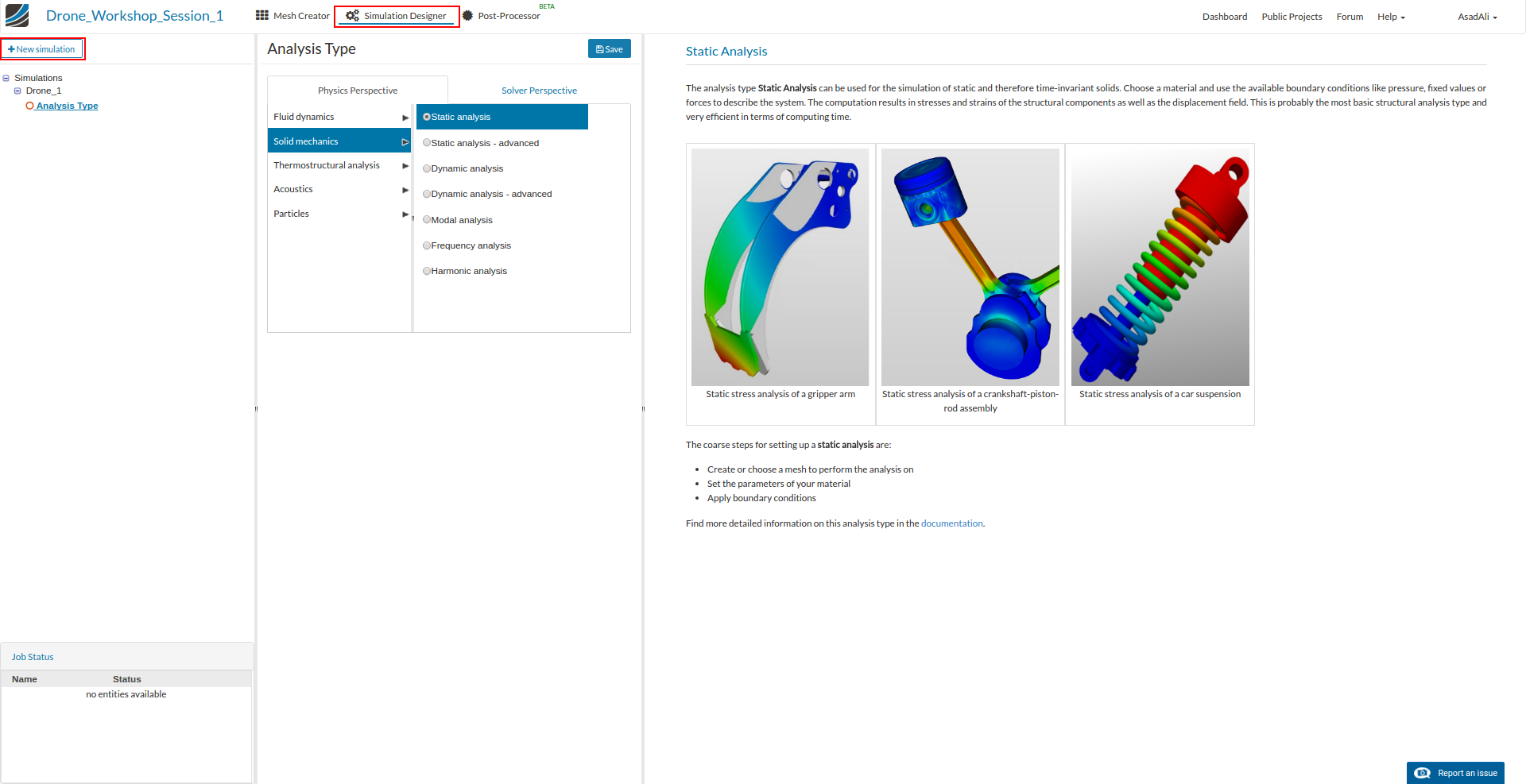
You will be notified when the project has been imported and it will be added to your Dashboard. First select the project and then click on the ‘Simulation Designer’ button on the main ribbon bar and then on the ‘New simulation’ button to create a simulation run. This will open an additional column in the middle. Here you can select which kind of simulation you want to run. In our case we will run a Fluid dynamics simulation of an incompressible fluid.
Now you can define some additional settings. First of all choose the k-omega SST turbulence model. This is necessary since the airflow around the propeller will be highly turbulent. Then choose Steady-State from the drop down field below. This means that we will simulate the stationary flow field. Finally save your settings, which will create additional items in the project tree on the left side.
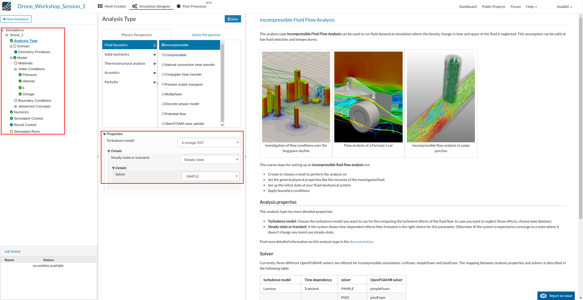
Going forward, this tree will guide us through all the necessary steps. Please note that some of the items are optional.
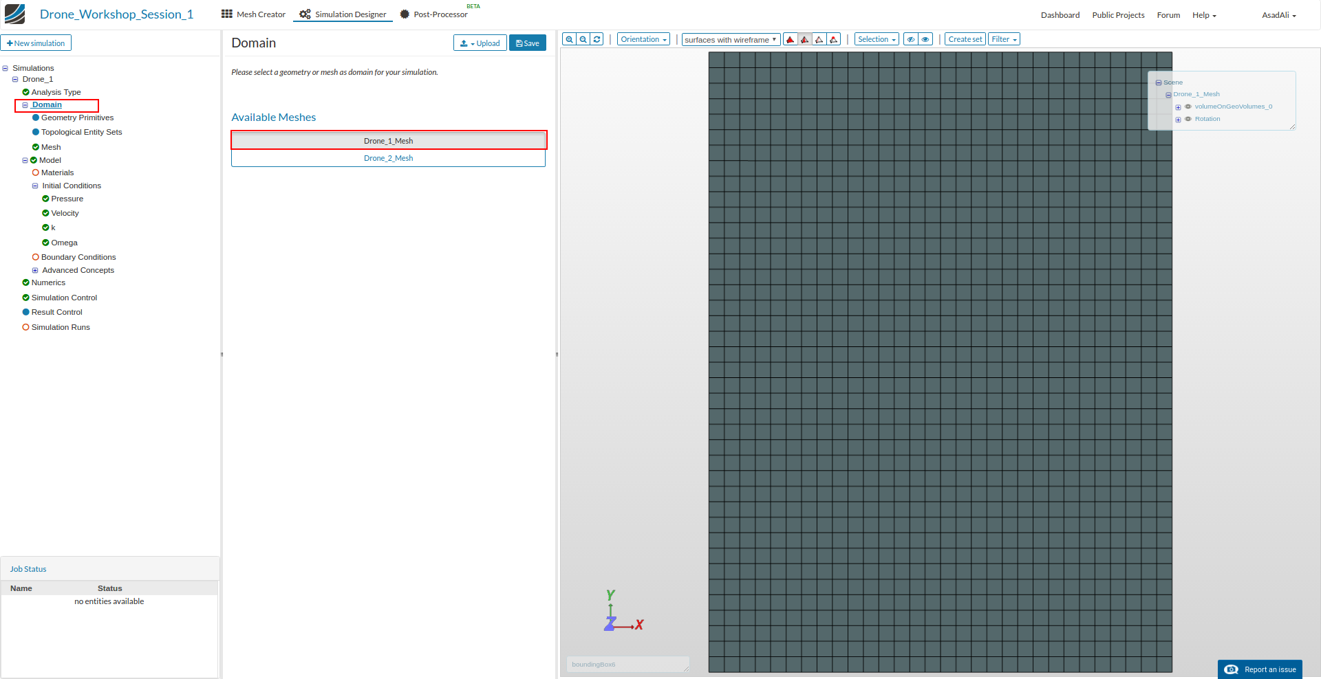
Next you have to specify which mesh you want to use for your simulation. Click on Domain item in the project tree and select Drone_1_Mesh from the menu. Don’t forget to save your selection.
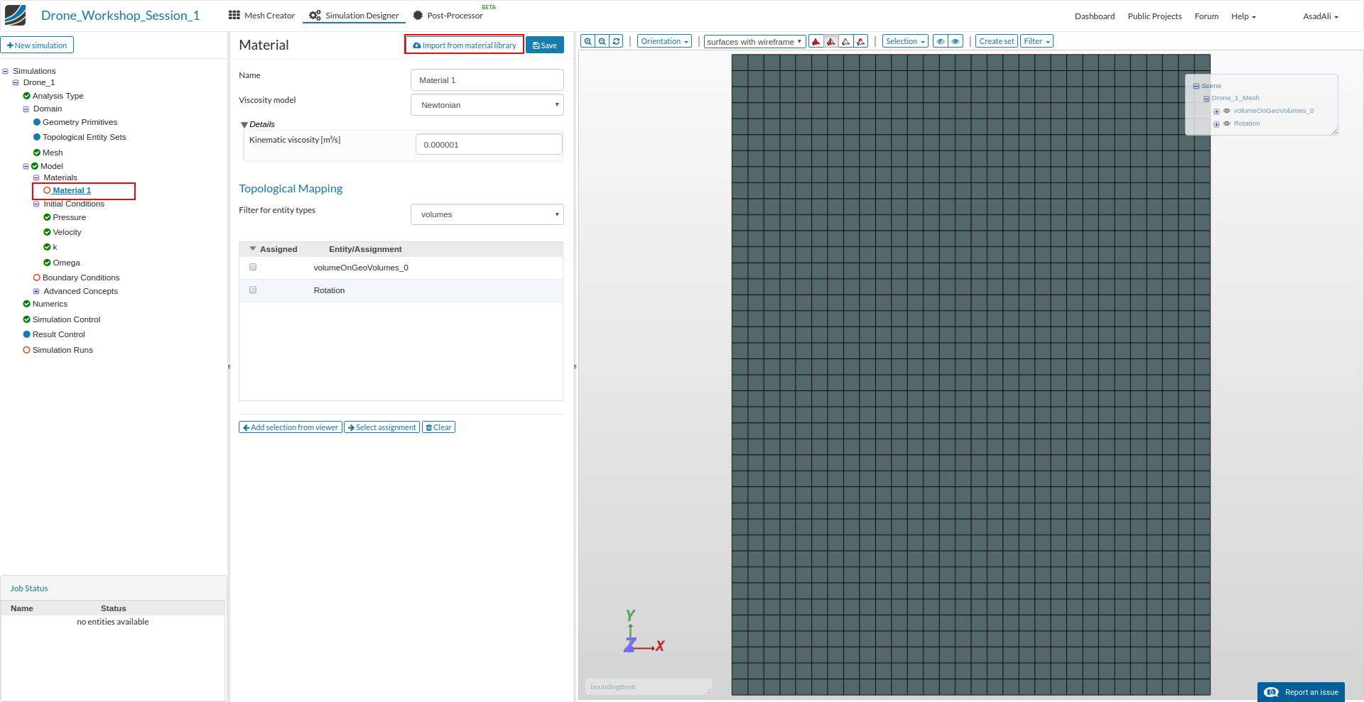
Now we have to specify the material properties of the fluid by defining the kinematic viscosity. Click on the Materials sub-item in the project tree.
This will open a new middle column windows where you can assign fluids to your mesh. SimScale also comes with a material library which we will use. Click on the Import from material library button
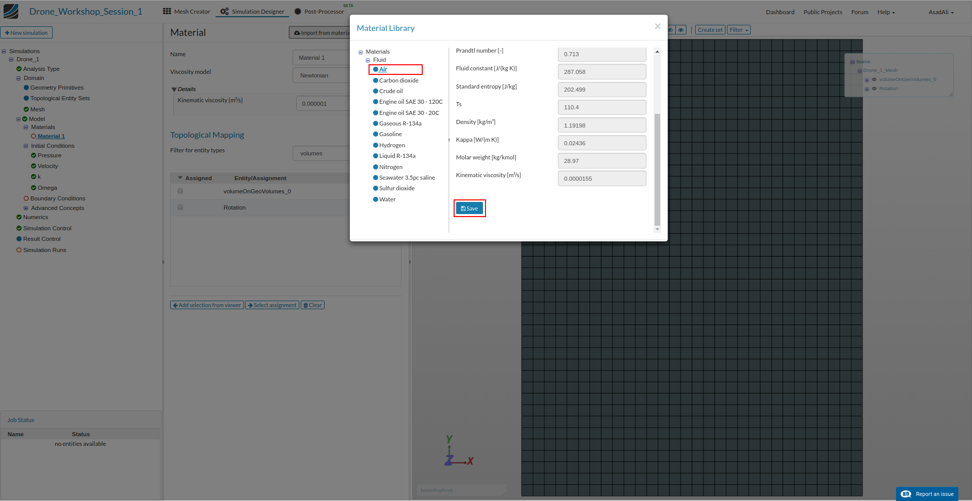
Here choose Air from the list and save your selection.
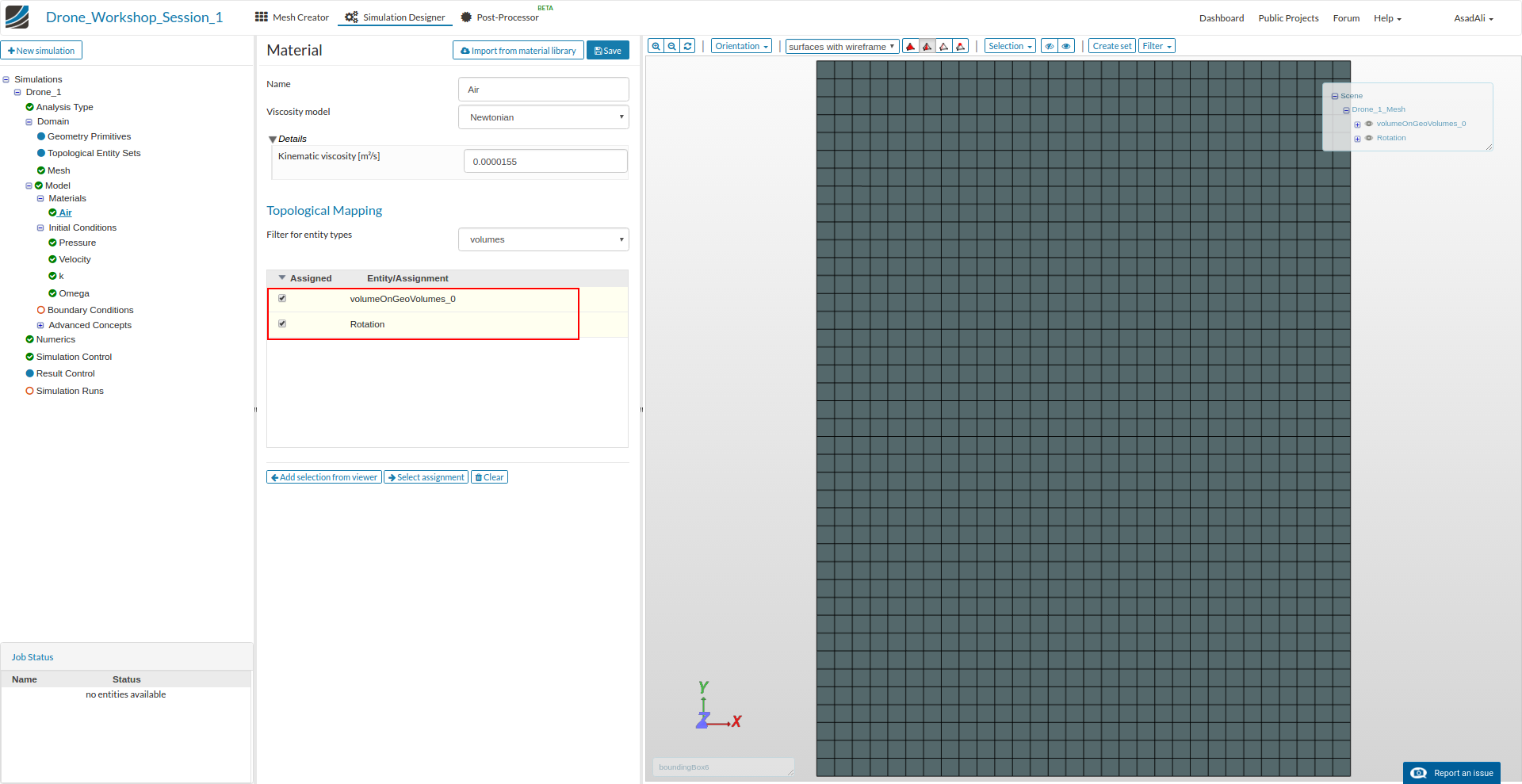
Finally we have to assign which parts of the mesh should be this material. Since we are only dealing with air select both volumes from the list.
The next item Initial Conditions can be skipped since the default values are fine for our simulation setup. For the sake of completeness, however, a short explanation about the meaning of this settings:
The Initial Conditions define the initial values for all physical quantities like pressure, velocity, etc. To understand this you have to keep in mind how engineering simulation actually works: Since the mathematical equations which describe the motion of fluids can only be solved numerically, the solver needs an initial solution to iterate. In some special cases it can be necessary to adapt this in order to make the simulation more stable. But this is not necessary in most of the cases.
Now you can start to specify the physical behavior of the drone and its interaction with the environment by defining the Boundary Conditions for all faces of the mesh.
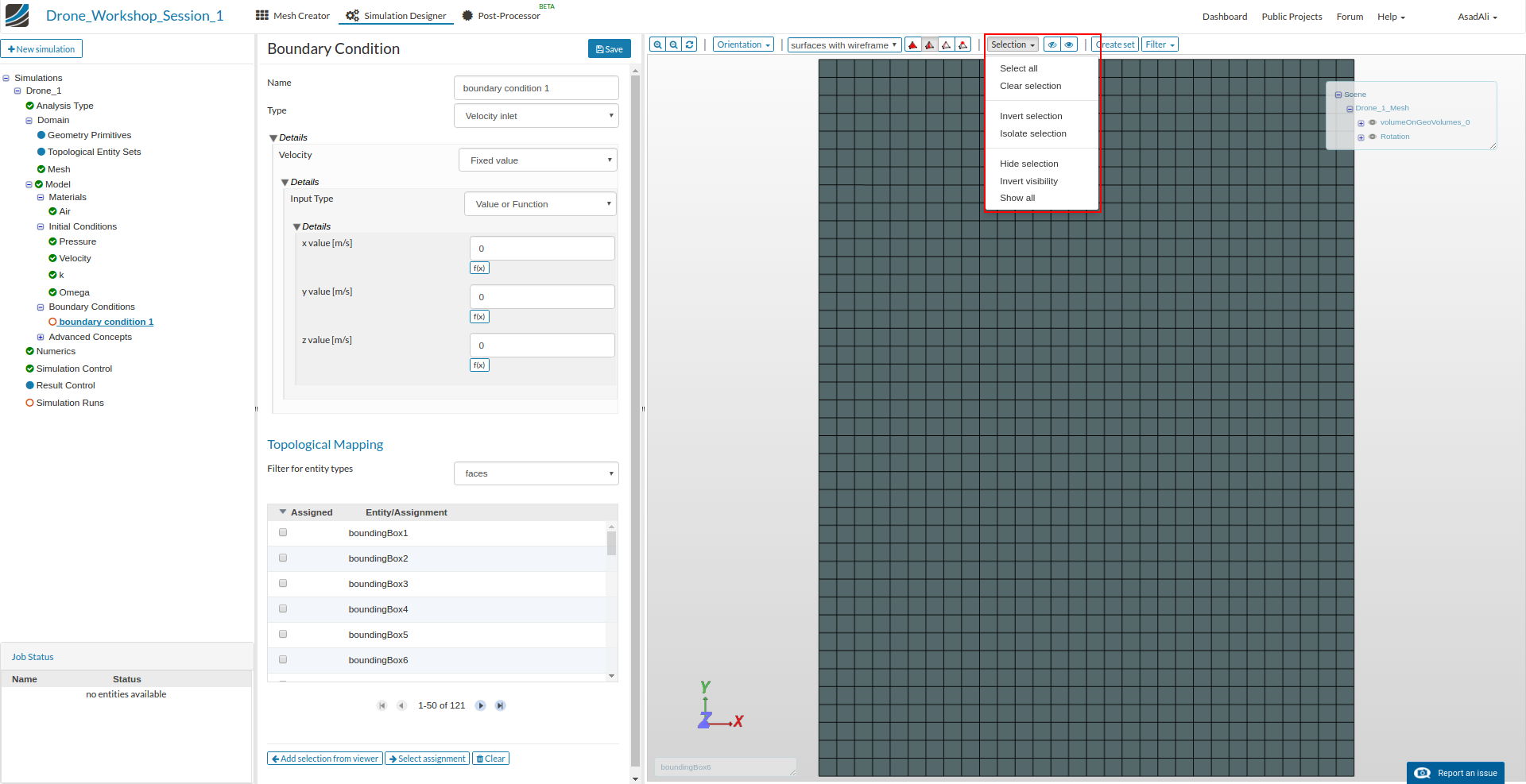
Click on the Boundary Condition item in the project tree which will again open a new column in the middle of the windows. Here you can see an overview of all boundary conditions which are applied to your mesh. To add a new Boundary Condition, click New

This will add a sub-item to the project list and open a new window where you can define the boundary condition. Here you can define a name for the boundary condition, choose the type and assign it to faces by using the list below.
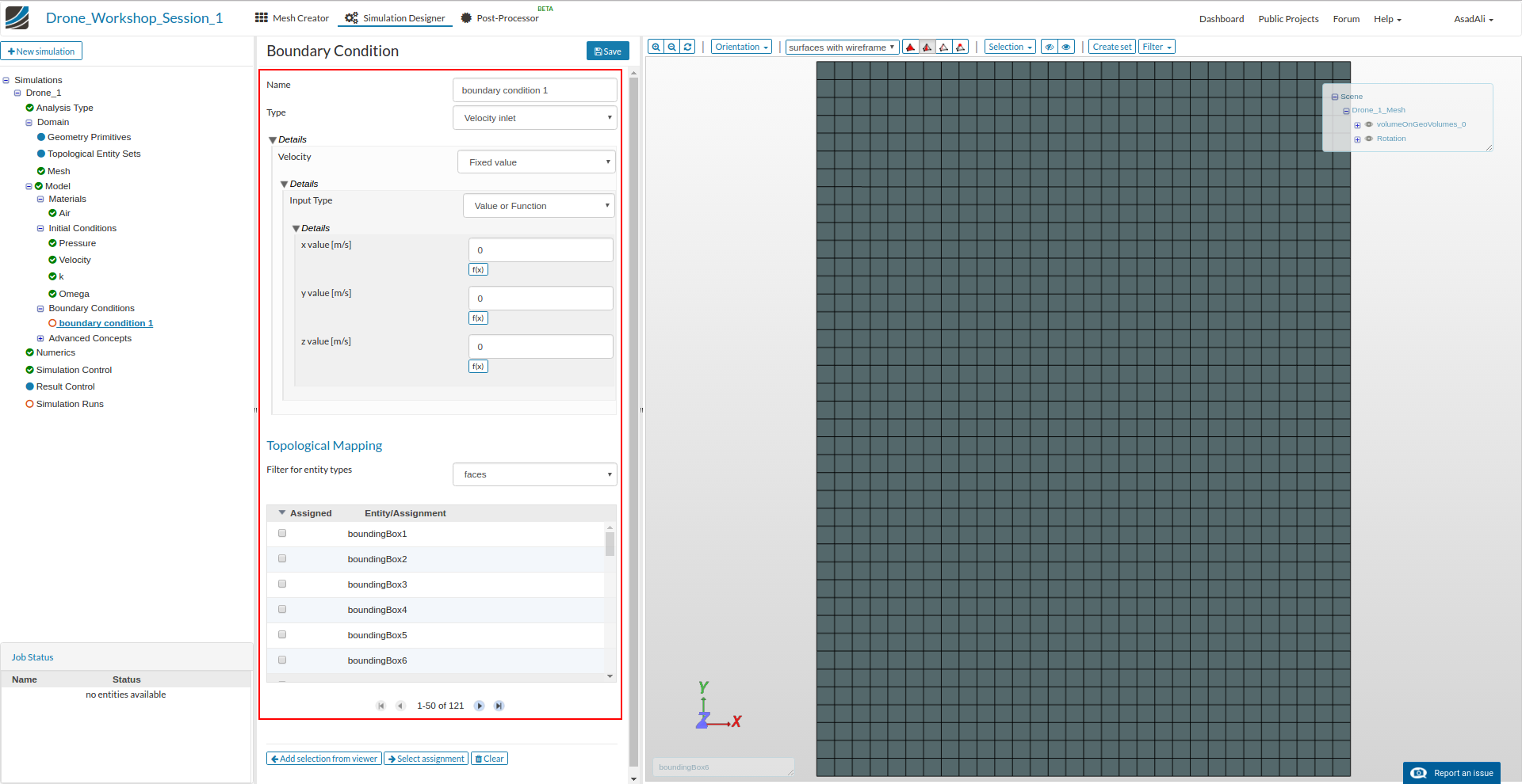
It is also possible and recommended to select the faces which you want to assign to the boundary condition graphically. You can select the faces in the 3D model window by clicking on them with the left mouse button; to add them to the list, just click on the Add selection from Viewer button in the middle column.
Since the full mesh domain is displayed, it is necessary to hide these faces in order to be able to select the inner faces. For this, select the faces you want to hide and click on the Hide Selection button from the drop down menu on top of the 3D model windows. Note that you can unselect faces by re-clicking on them.
Now we will create the 4 necessary boundary conditions.
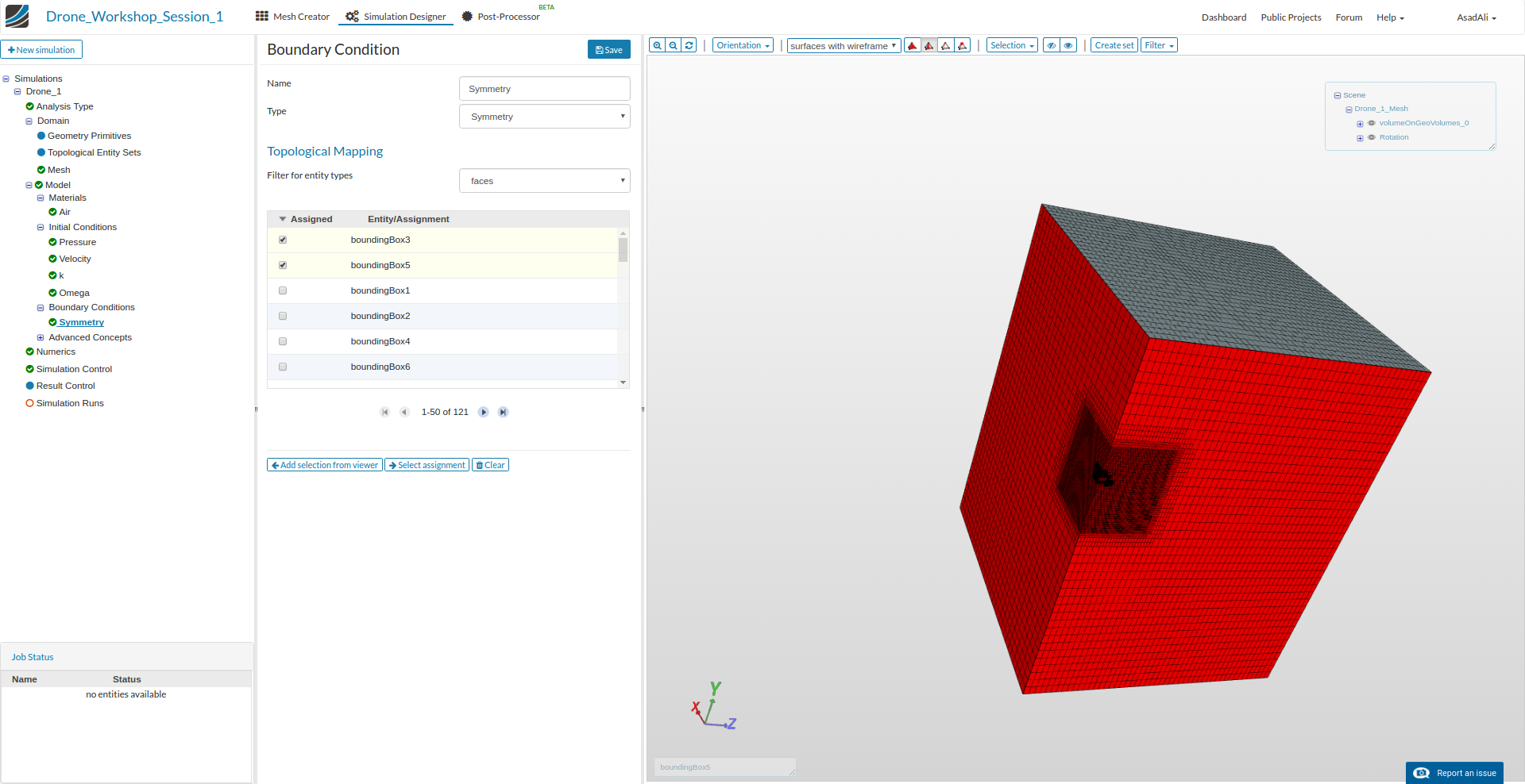
Symmetry
This boundary condition is required because we are using a quarter model of the drone. Select Symmetry as the type and the 2 surrounding faces (boundingBox3, boundingBox5) which intersects with the drone body.
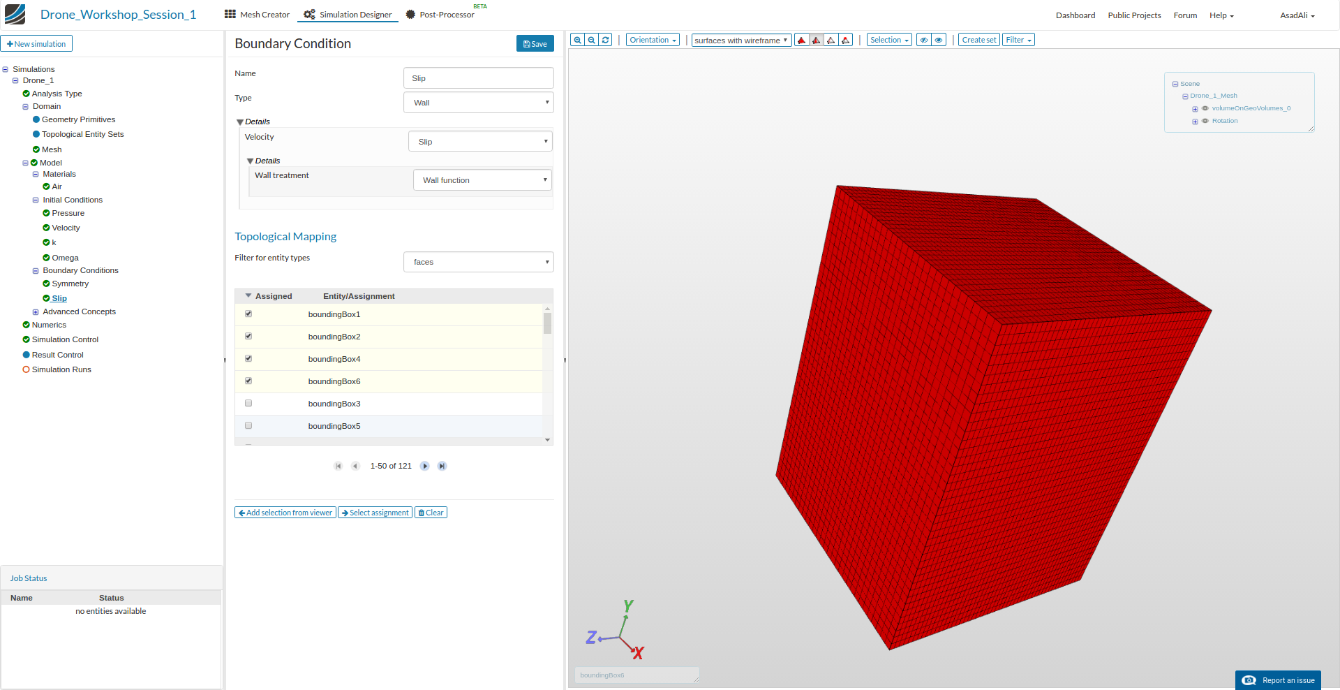
Slip
As already discussed, this boundary conditions will reduce the interaction of the other surrounding walls. It is necessary because these walls do not exist in reality.
Select Wall as the type and Slip for Velocity and Wall function for the wall treatment. Now select the remaining surrounding faces (boundingBox1, boundingBox2, boundingBox4, boundingBox6) and add them to the list of faces.
Now it becomes a little fancier, but don’t worry! ![]()
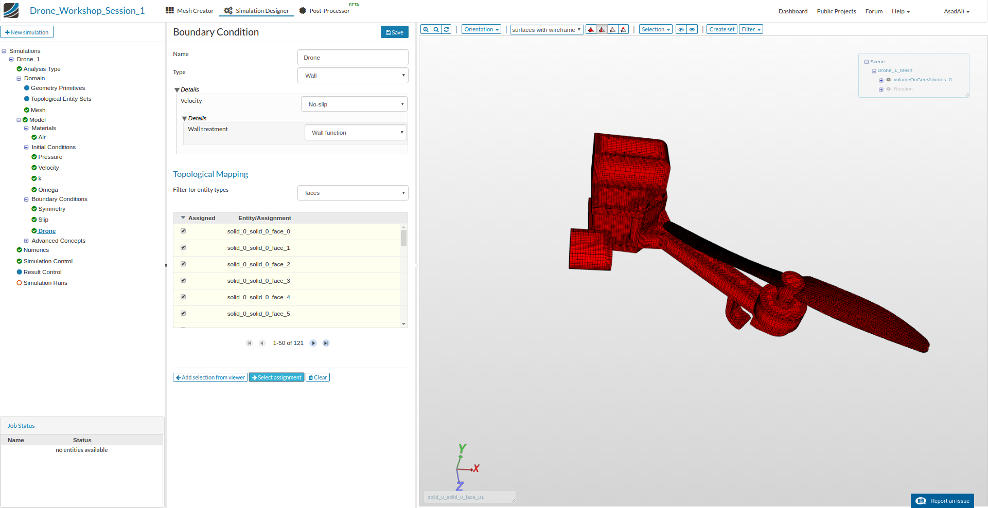
Drone
Next we will apply the boundary condition to the drone. Select Wall as the type and No-Slip for Velocity and Wall function for the wall treatment.
To select the right faces, it is necessary to hide the surrounding surfaces as described in the previous section. You will notice that there is a cylindrical surface around the propeller which you also have to hide. Now you can select the surfaces of the drone. Be sure to select EVERY surface of the propeller (some of them are very small,) including the upper shaft of the propeller. You can also use select all in the drop down menu, which will select ALL visible faces.
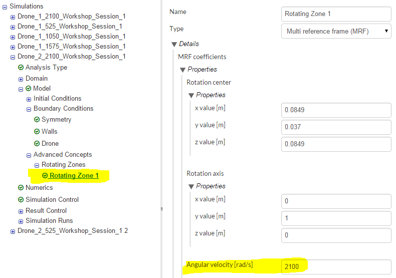
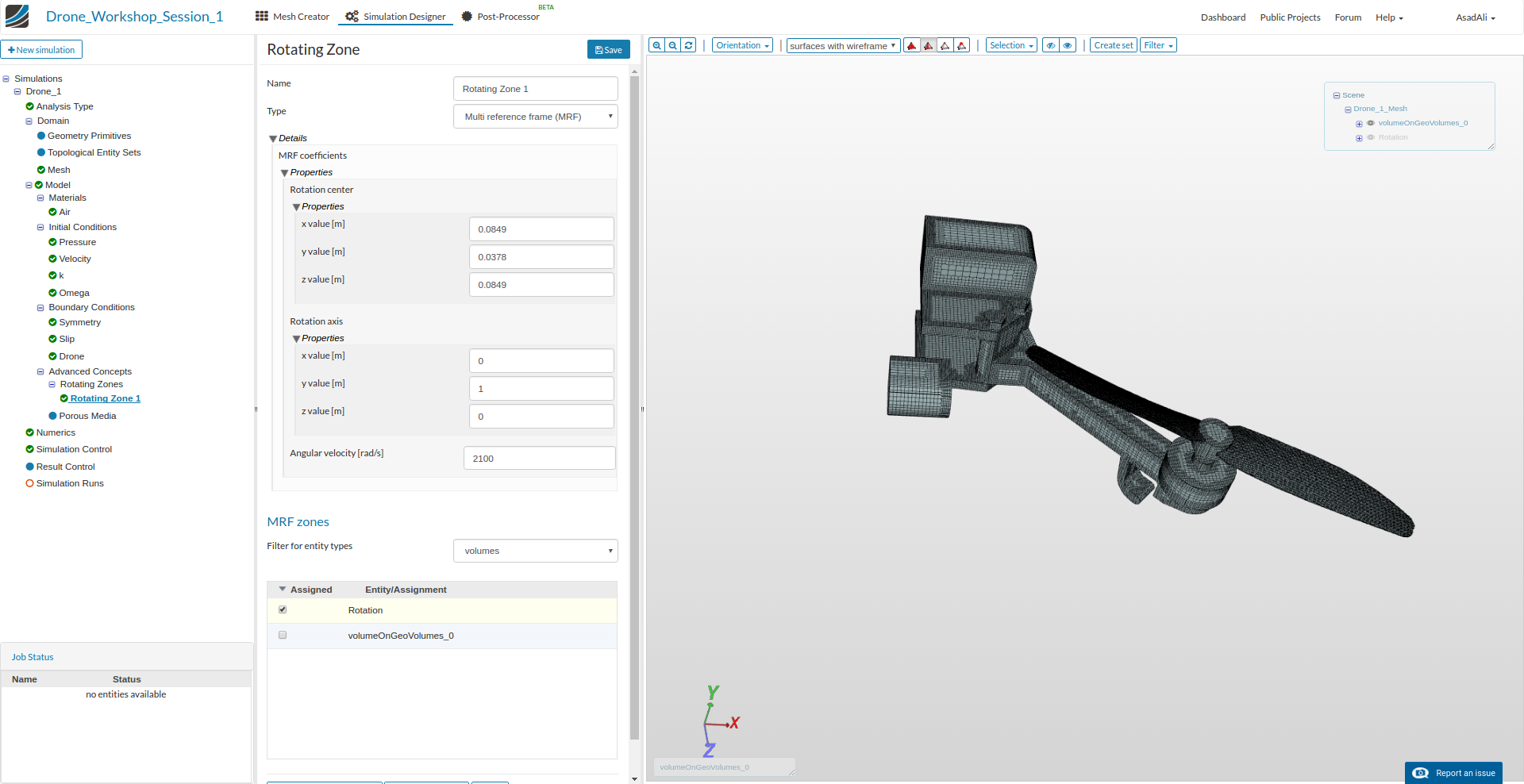
Next we will assign the rotation to the propellers. Click on the Advanced Concept item in the project list and click then on the Add rotating zone button in the middle column. This will open a new middle column menu where you can specify the rotation.
The mesh includes two zones. One of them (Rotation) includes all cells around the propeller. The only thing you have to do is specify the Rotation center (0.0849, 0.037, 0.0849), the Rotation axis (0, 1, 0) and the angular velocity of the rotation which is 2100 rad/s (this is equal to 20000 rpm). Last, select the cell zone Rotation from the list bellow and save.
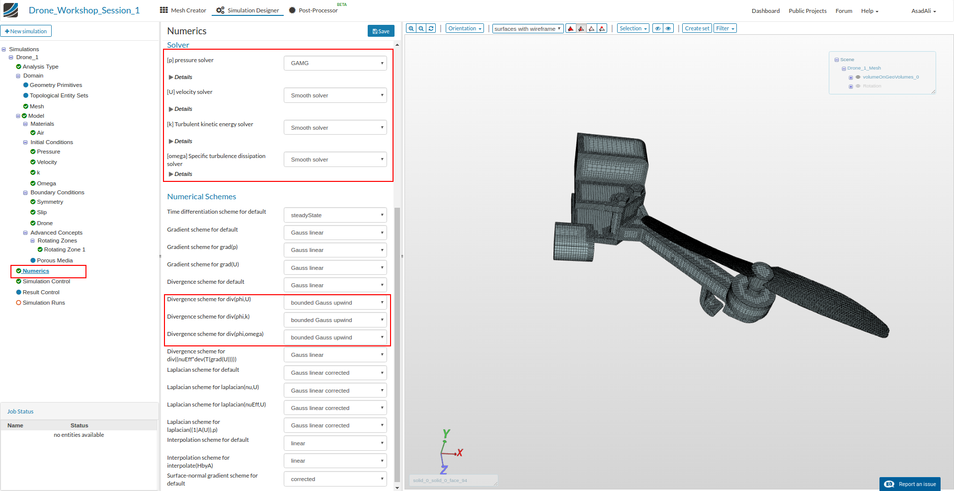
Now we have to modify some of the numerical settings. This is not absolutely necessary but it will help to reduce the simulation time and make it more stable. Click on the Numerics items in the tree and change the settings and values according to the image below (Please note that you have scroll down).
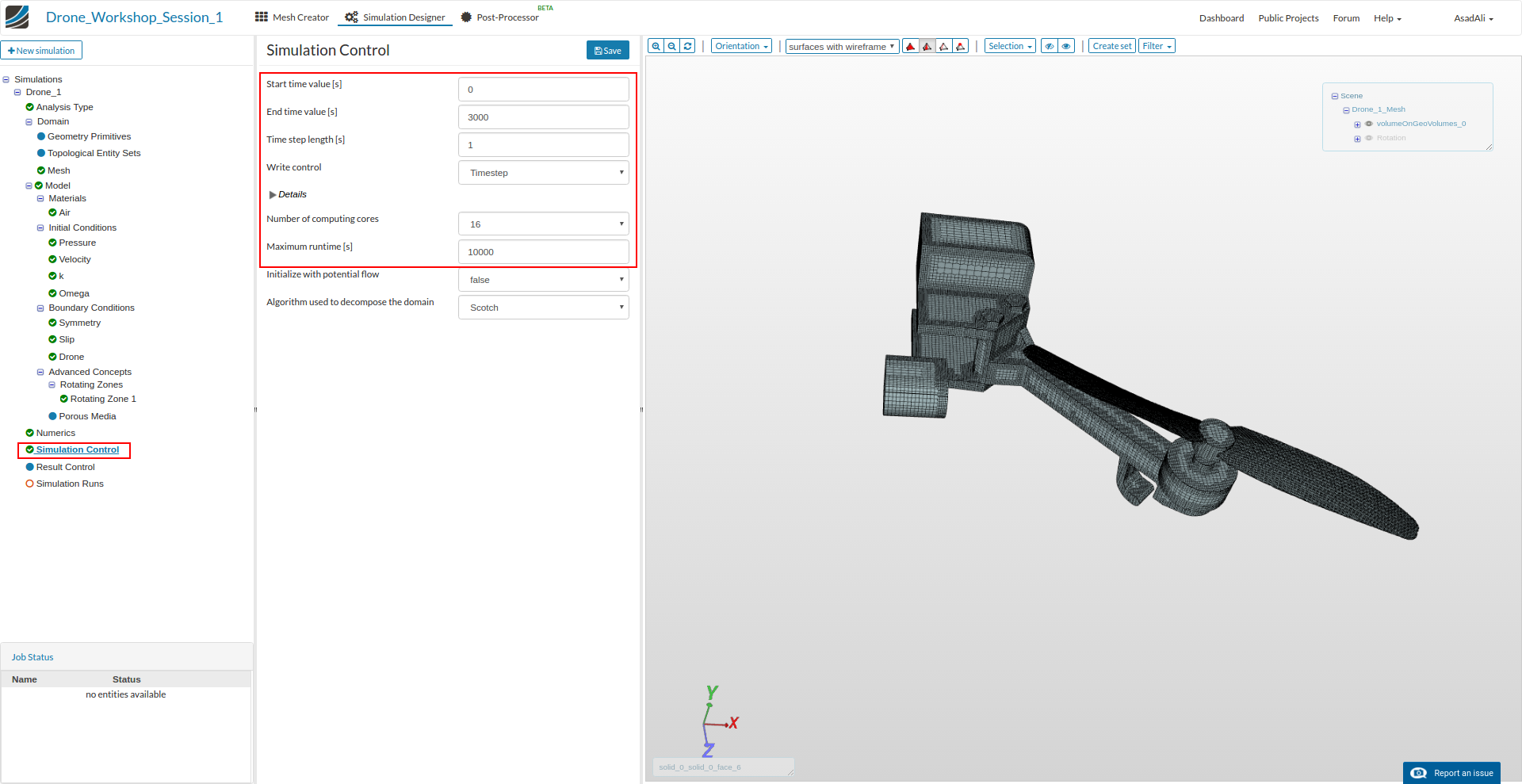
Click on the Simulation Control item in the project tree to specify how fast and accurate you want the simulation to be computed.
Choose 0 as the Start time value and 3000 as the end time value. The time step length must be 1 and the write interval 3000. Finally, choose 16 computing cores from the drop down menu and define a maximum runtime of 10000 seconds (this is the time after which the simulation run will automatically be cancelled).
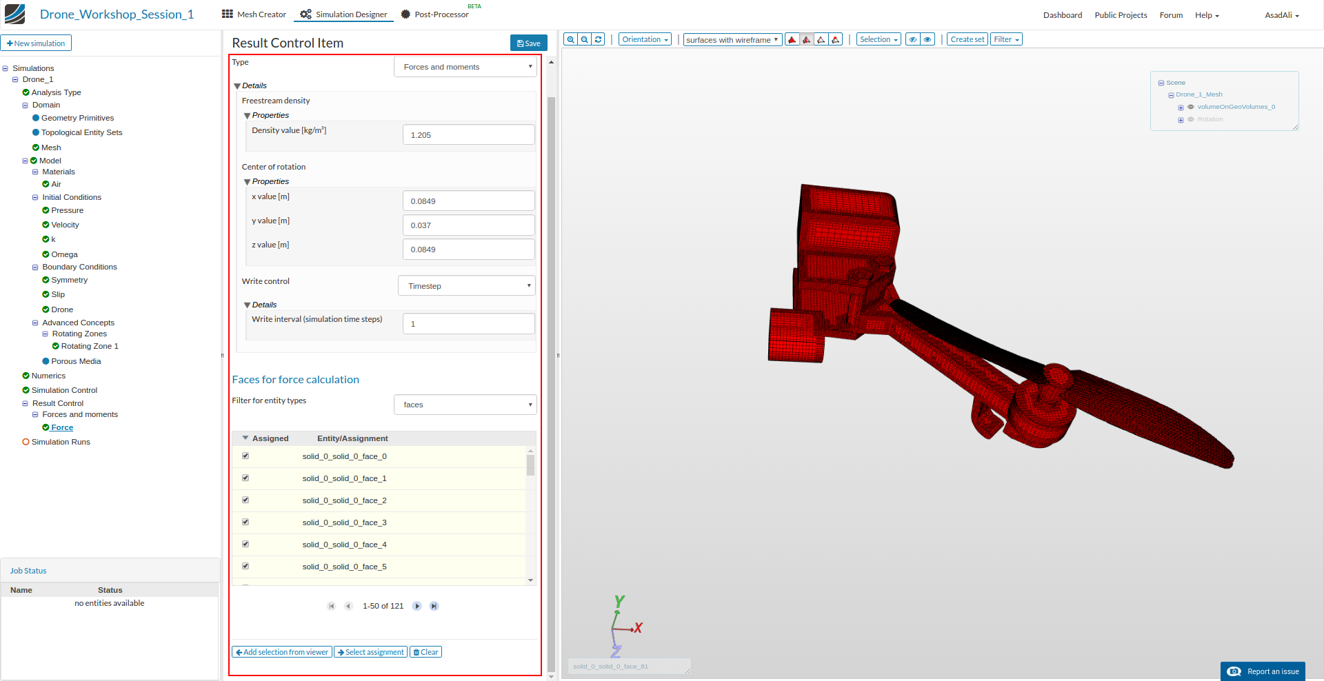
To “measure” the lift force of the drone we have to add Result Control item. Click on the corresponding item in the project tree and click on New for Add Forces and moments item.
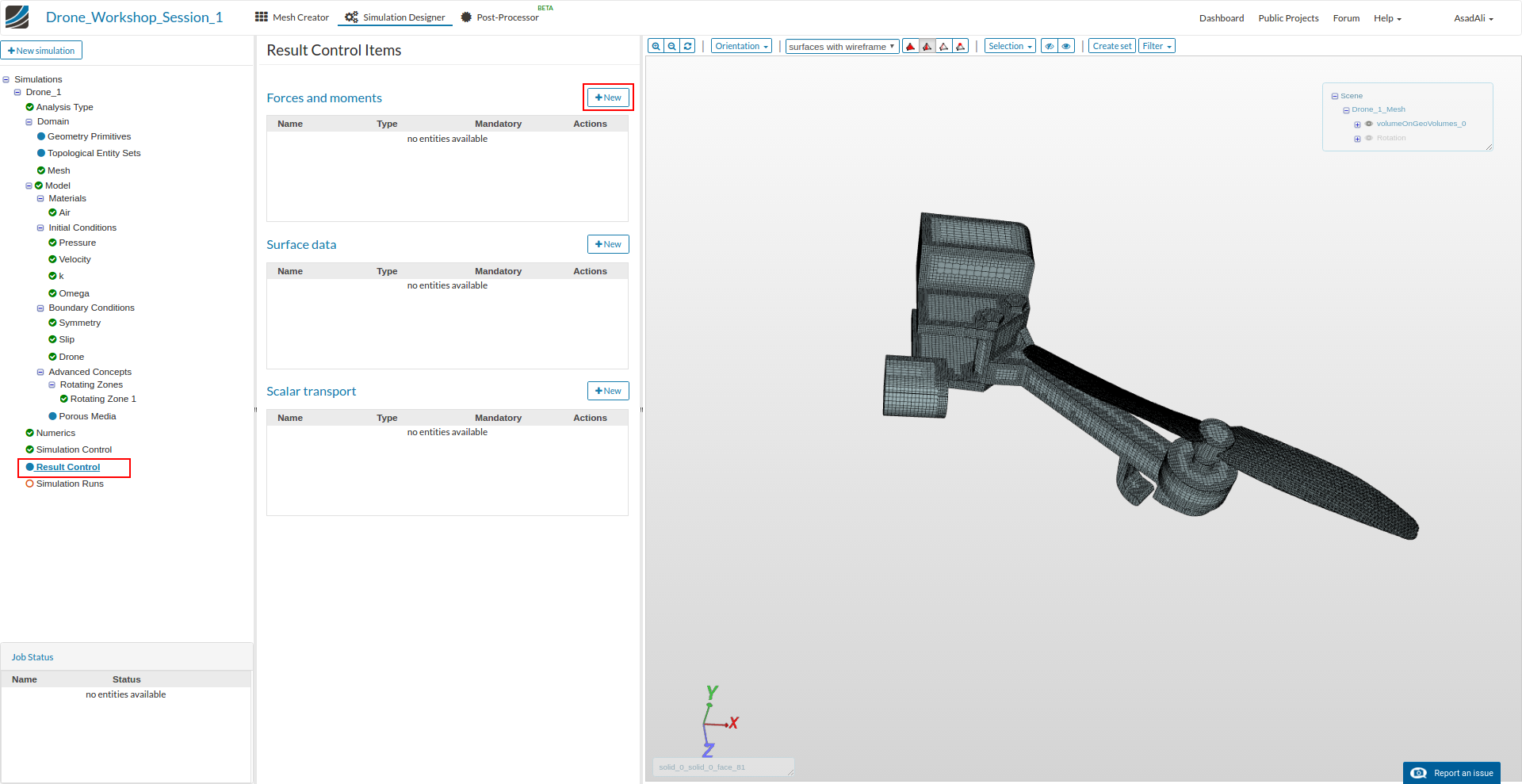
Choose Forces and moments as a type, define a Density of 1.205 kg/m³ and (0.0849, 0.037, 0.0849) as the Center of rotation. Skip the remaining settings and add all surfaces of the drone to the surface list (workflow according to the drone boundary condition)
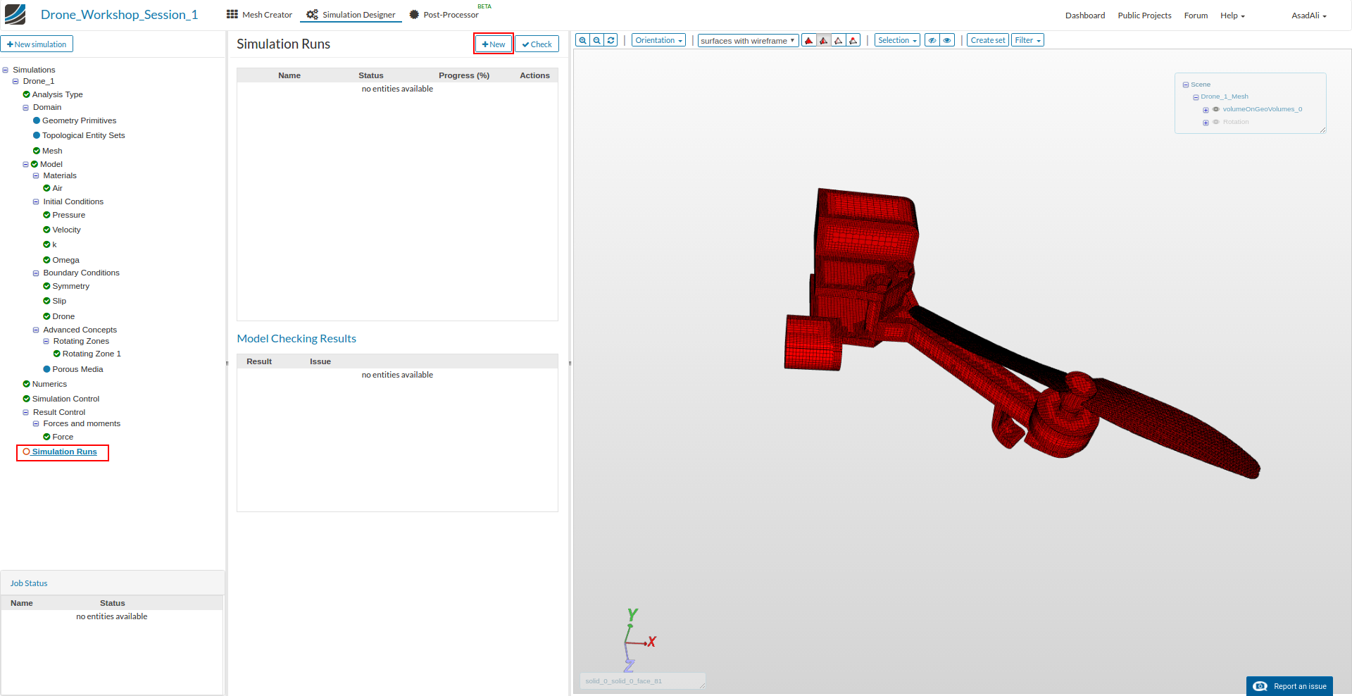
To start the simulation, click on the Simulation Run item in the tree and click on the New against Simulation Runs. This will create a snapshot of your simulation settings as a new sub-item.
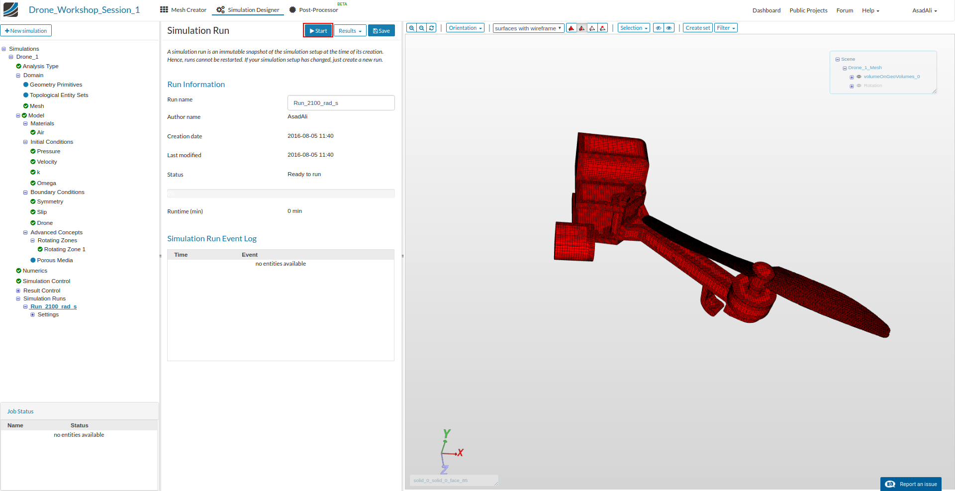
You can now start the simulation run by selecting it from the project tree and then click on the Start button.
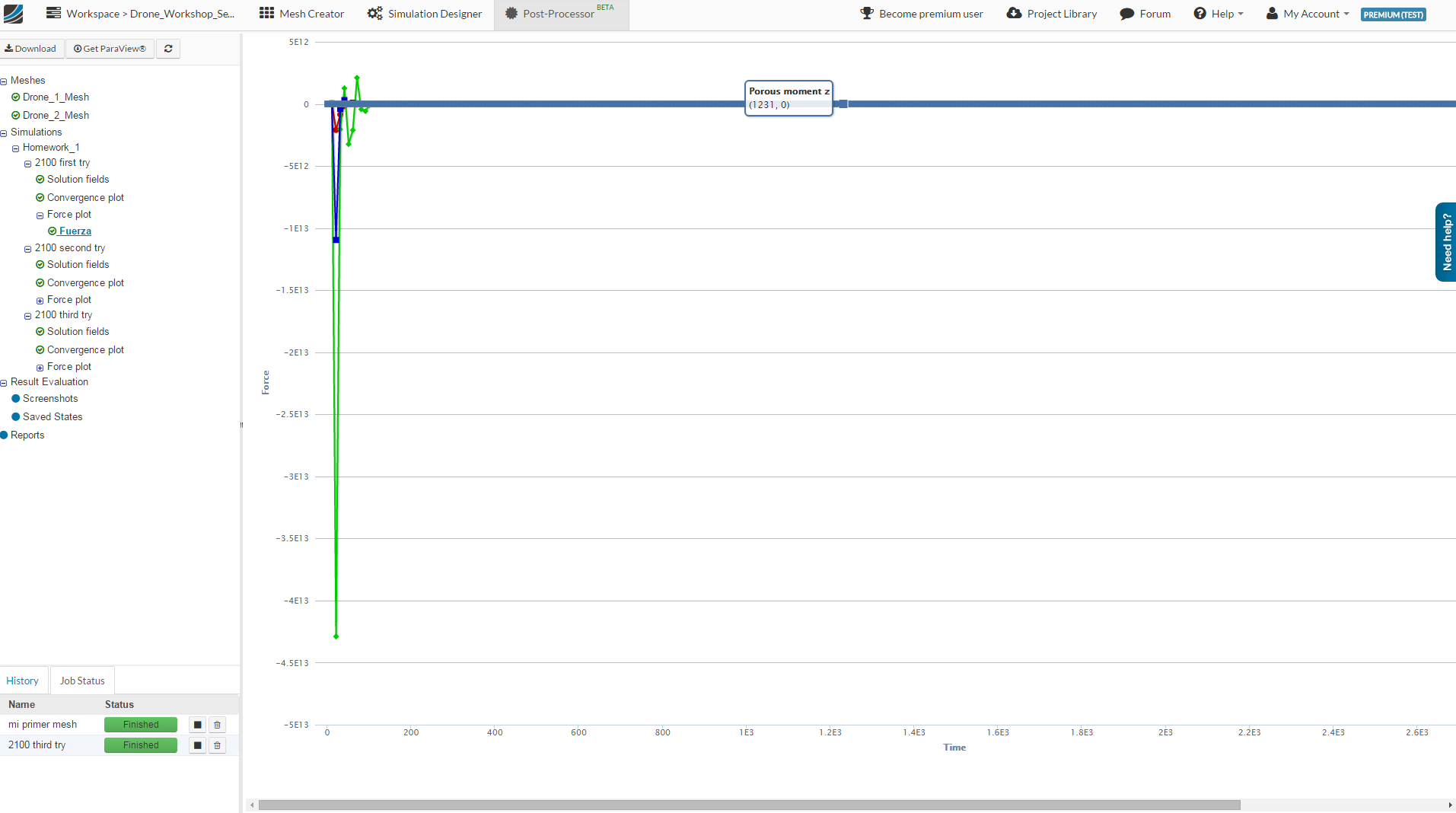
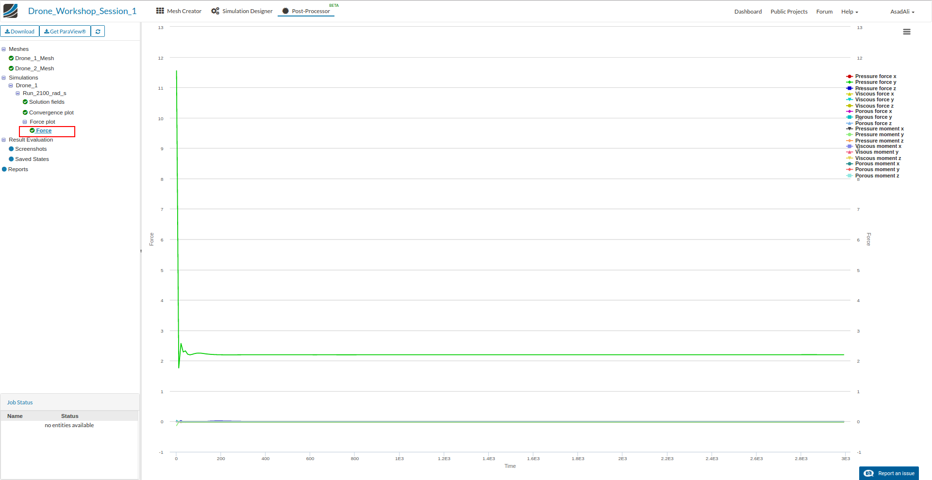
You will be notified by email when the simulation is finished. To check the results of the lift force, click on the Post-Processor button in the main ribbon bar. On the left side is a result tree, where you can find all simulation results.
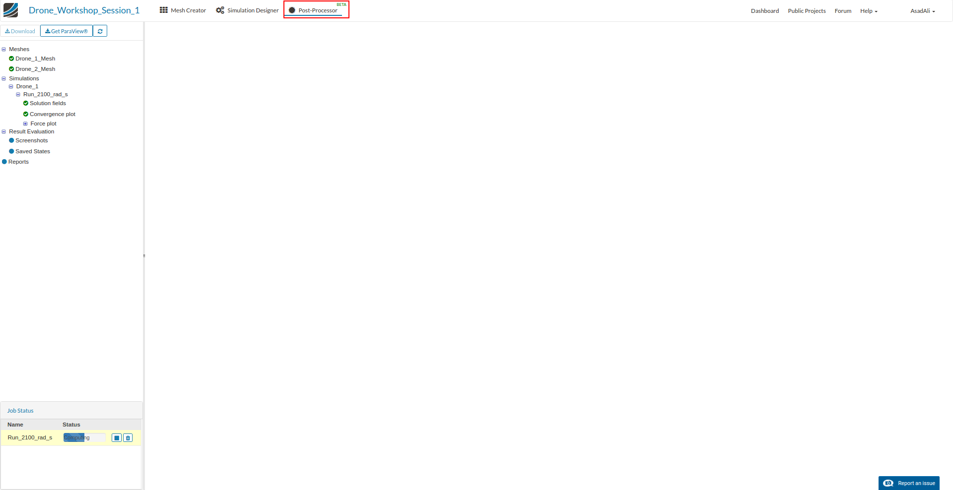
Click here on the sub-item Force plot and select the related plot. This will open a graphical chart on the right side where you can see the calculated forces and moments against the number of iteration. Moving your mouse over the line for Pressure force y will show you the lift of the drone.
Congratulations, you have completed the Homework of Session 1 - Level 1 and can now move on to the next level: