NOTE: This tutorial was updated on 08/2016 to match the updated version of the platform
If you would like to watch the second session of the Drone Workshop again or in the case you missed it, you can access the full recording below.
 - Static Structural Simulation of a Drone Part")
Level 1
Exercise

Our aim is to investigate the displacement of the drone arm for different lift forces. Therefore we will create a mesh of the arm and simulate the structural behavior of it for different forces (0.75N, 1.5N, 2.25N, 3N).
Your final homework project should contain 1 mesh and four simulation runs. You can submit your homework using the form.
Step-by-Step
First of all you have to import the geometry into your SimScale workspace. For this, you only have to click on this link and a project with everything you need will be added to your workspace. Please note that this can take several minutes.
Meshing
- In the Mesh Creator tab, click on the geometry Drone_Arm
- Then, click on New Mesh button in the options panel.
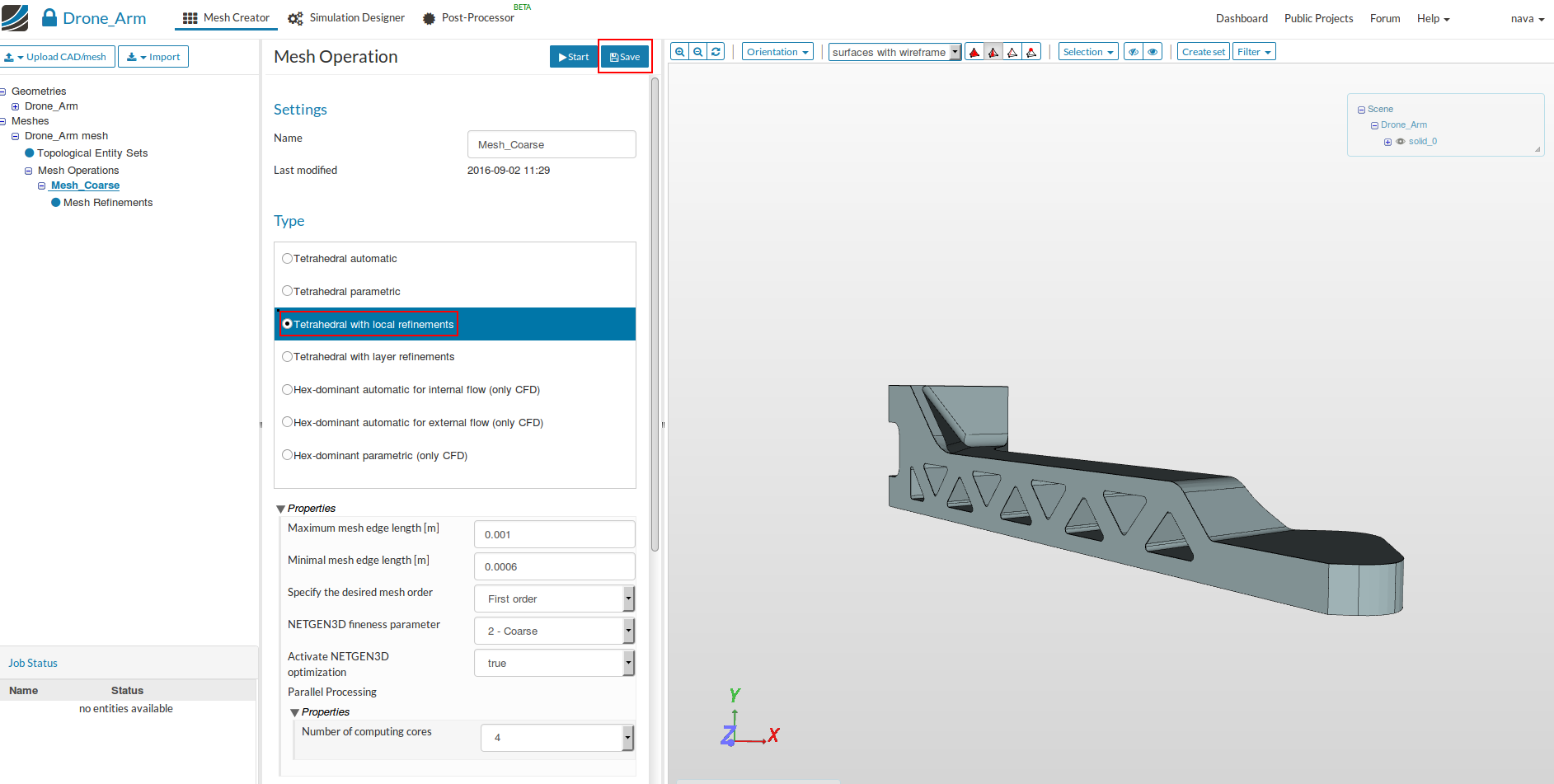
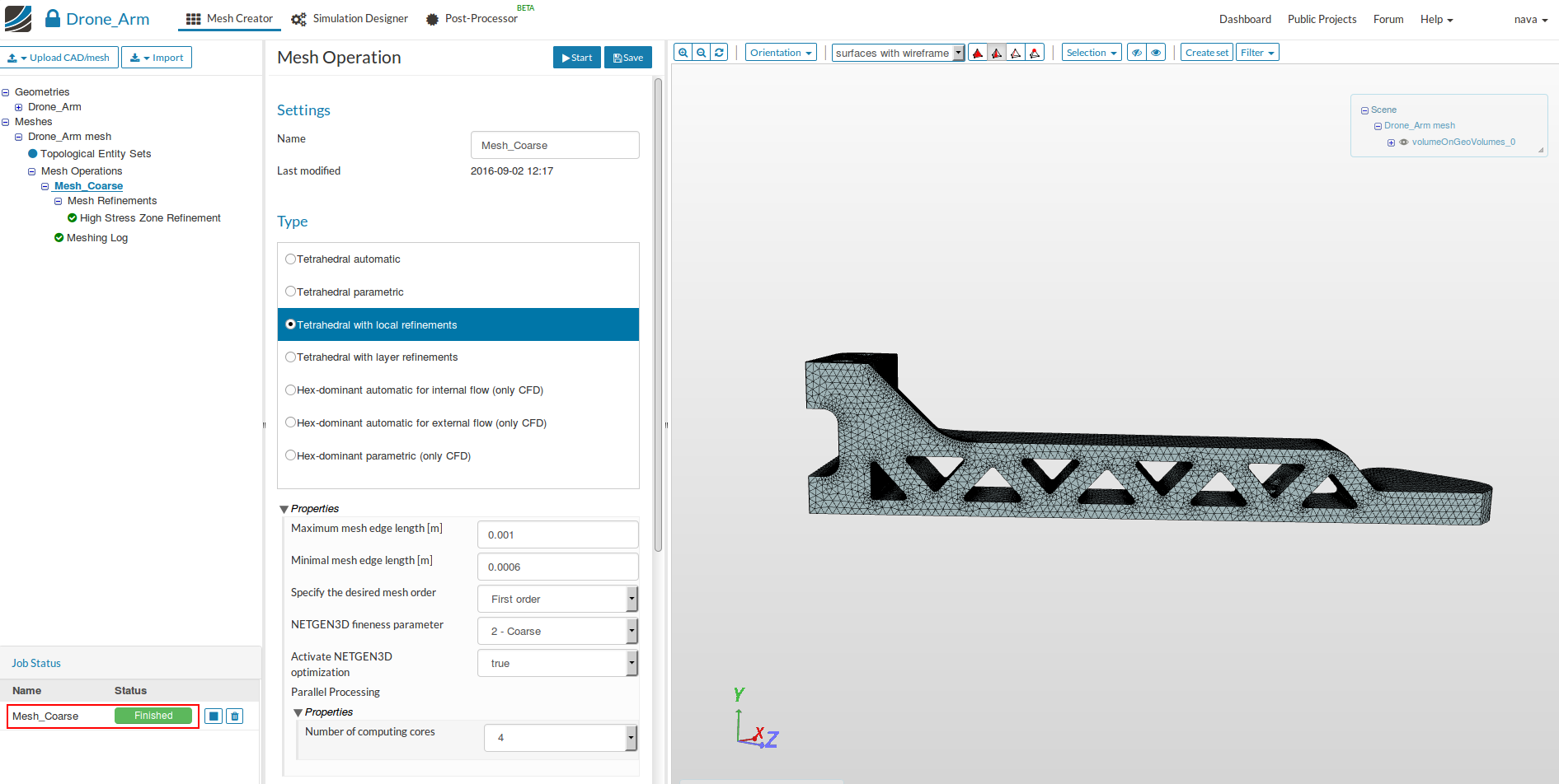
- Select Tetrahedral with local refinements and define following parameters:
- Name: Mesh_Coarse (optional)
- Maximum mesh edge length [m]: 0.001
- Minimal mesh edge length [m]: 0.0006
- Specify the mesh order: First order
- NETGEN3D fineness parameter: 2 - Coarse
- Activate NETGEN3D optimization: true
- Number of computing cores: 4
- Click on Save to save the setting.
Now we have defined a range for the base mesh size which is fine for regions where we are not expecting high stress. Here you should keep in mind that, in general, the mesh size is related to the local accuracy of the simulation. It is therefore necessary to refine the mesh in curved surfaces with very small curvatures (fillets) where stress concentration is expected.
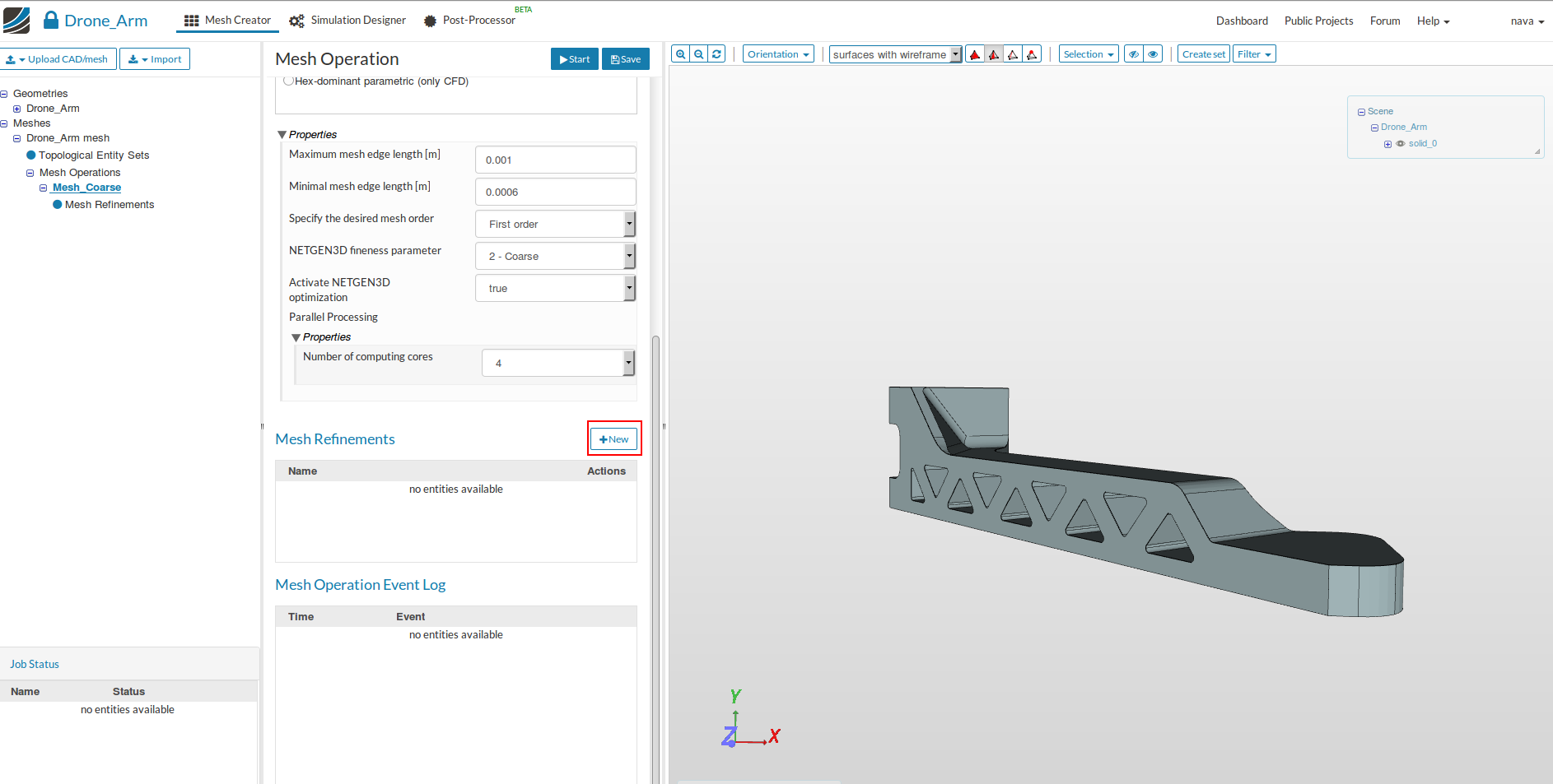
We will now apply local refinements on the faces which are curved surfaces.
- Click on the New button under Mesh Refinement.
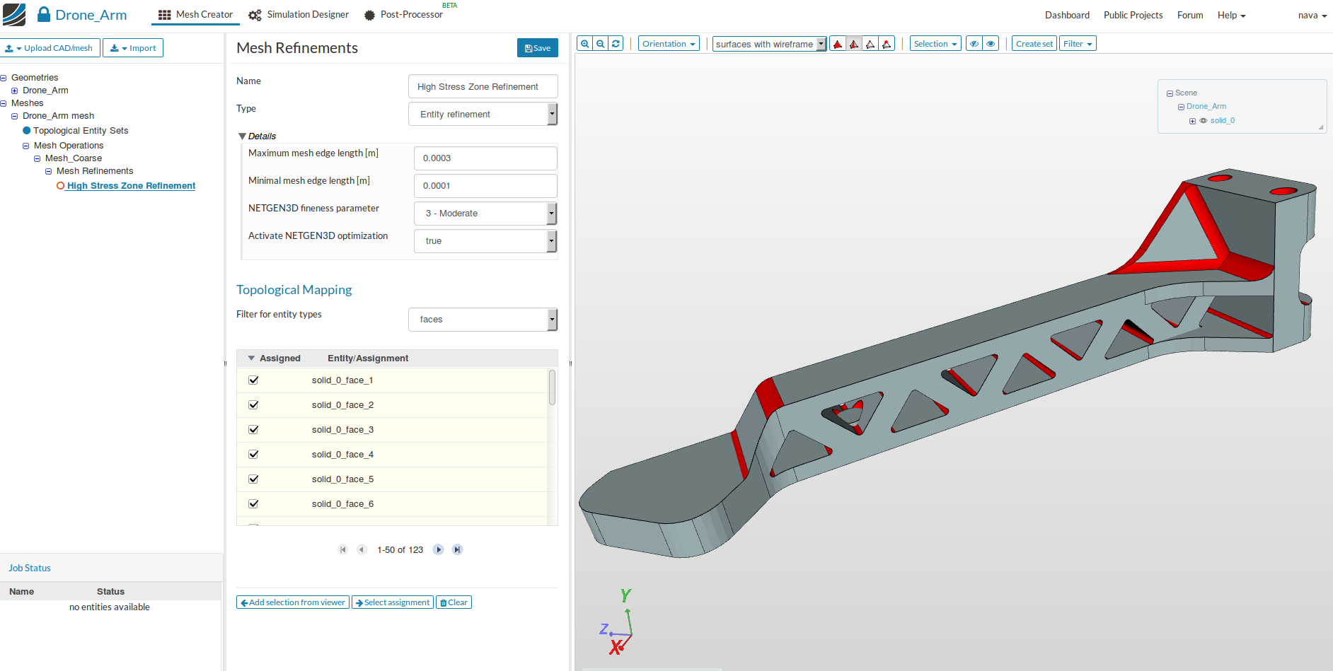
- Specify the following parameters
- Name: High Stress Zone Refinement (optional)
- Maximum mesh edge length: 0.0003
- Minimal mesh edge length: 0.0001
- NETGEN3D fineness parameter: 3 - Moderate
It is also possible and recommended to select the faces which you want to assign to the refinement graphically.
-
Choose faces for Filter for entity types and click on
 so that you can select the faces which you need to refine.
 -
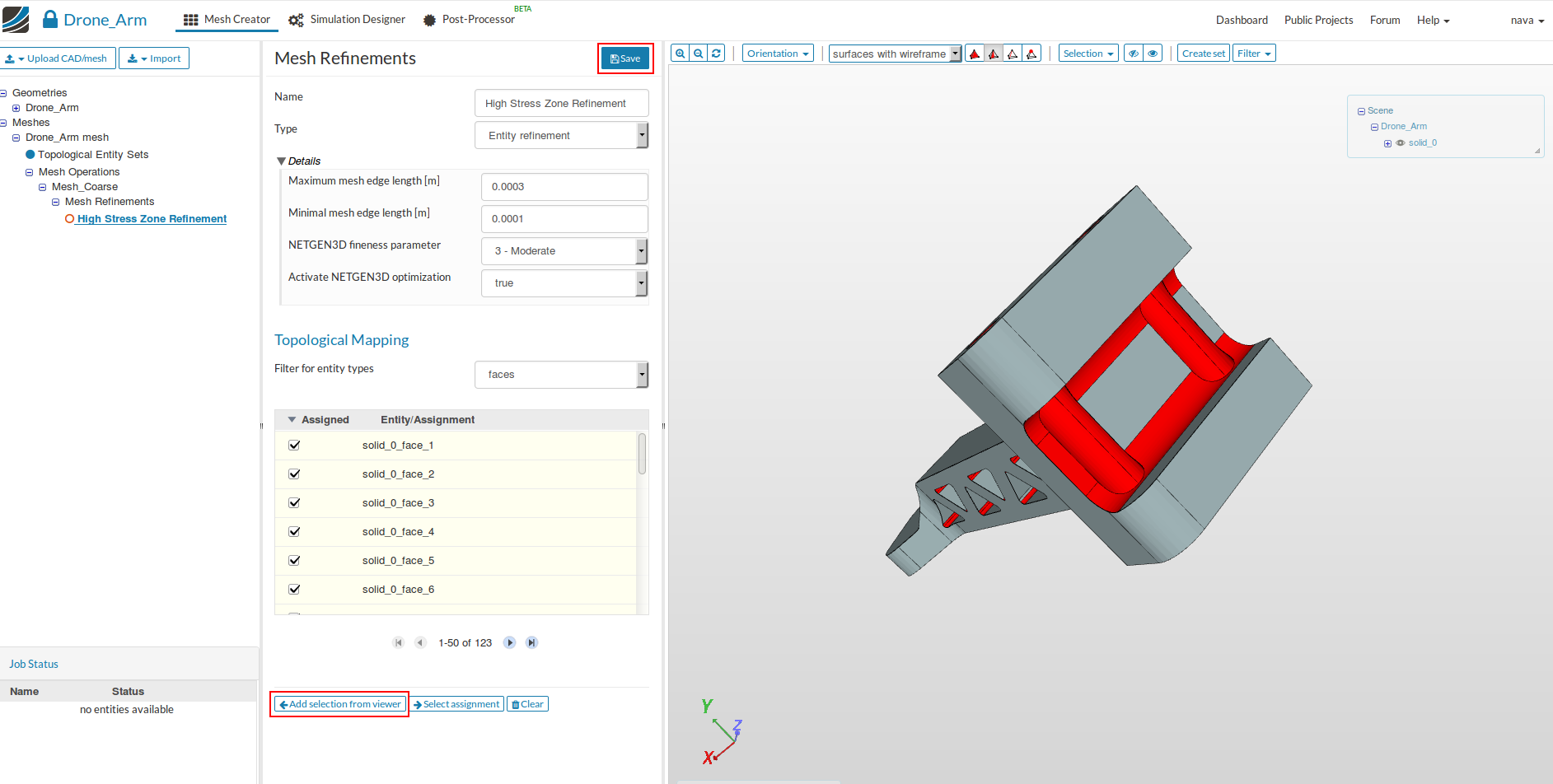
Select all the fillets and curved surfaces, click on Add selection from viewer to assign the selected faces and then click Save.
- Now our mesh is ready for computation. Click on the Mesh_Coarse in the project tree and click the Start button. The mesh computation will begin automatically and will take around 5 min to complete.

- Once the mesh computation is finished, you will see Finished status in lower left corner and in the viewer you will see the meshed geometry.
Simulation Setup
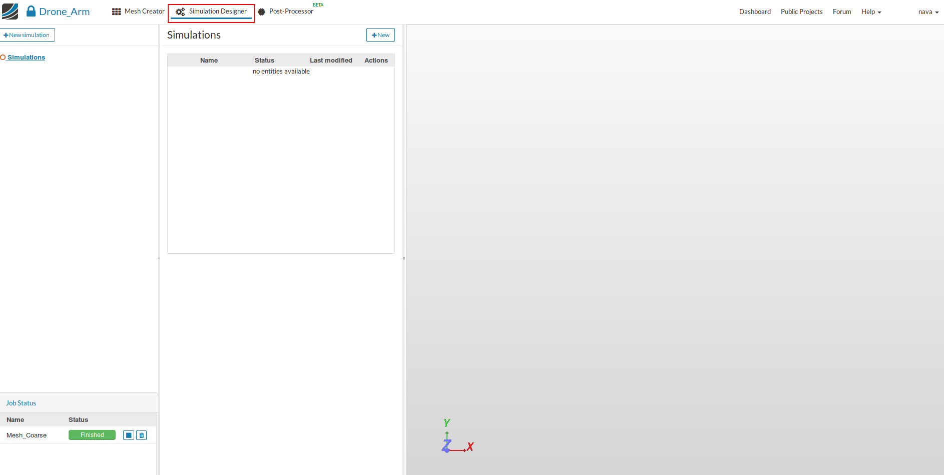
- After the mesh is completed we will set up the simulation. Click on the Simulation Designer tab.
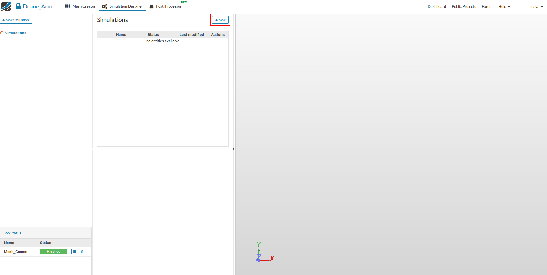
- Click on New button to create a new simulation and give it a suitable name- Load case-3N (optional).
- We don’t expect much deformation in this analysis (estimate of deformation can be calculated from beam equation). Therefore, we will select Static analysis as Analysis Types and then click on Save.

Going forward, this tree will guide us through all necessary steps. Please note that some of the items are optional or not necessary and will therefore be skipped
Domain selection
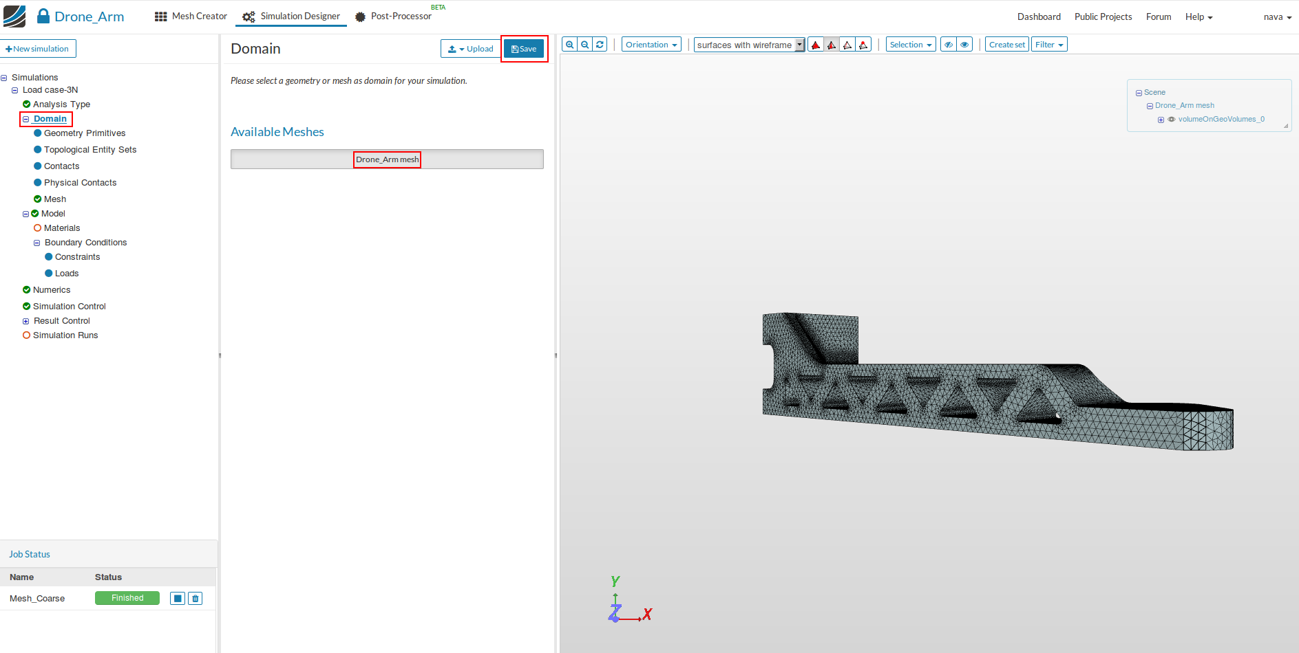
- Next you have to specify which mesh you want to use for your simulation. Click on Domain item in the project tree and select Drone_Arm mesh and then Save.
Select Solid Materials
Now you can define your new material based on your own material properties or access our Material Library which includes ready-to-use material models for several materials.
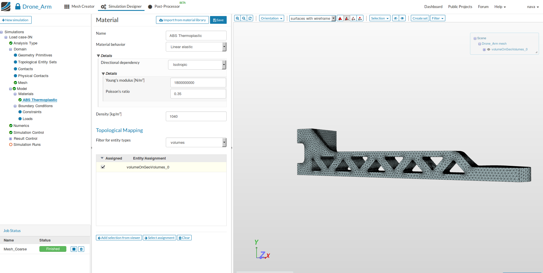
- We will manually define an ABS Thermoplastic. Click therefore on the Materials item in the project tree and then on New button to create a new material.
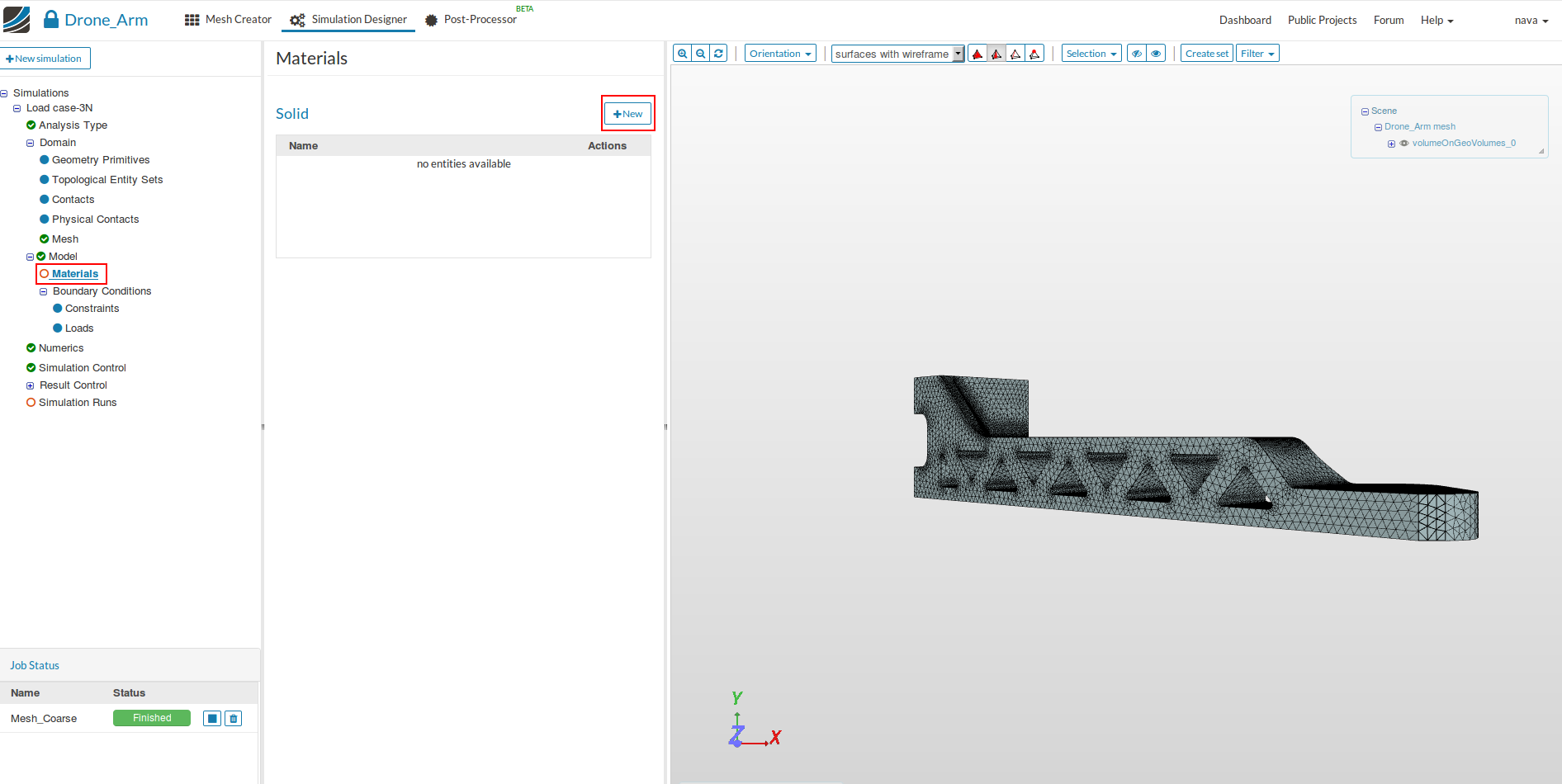
- Specify the following parameters:
- Name: ABS Thermoplastic
- Young’s Modulus [N/m2]: 1800000000
- Poisson’s ratio: 0.35
- Densiy[kg/m3]: 1040
- Now assign the material to volume of the arm (volumeOnGeoVolumes_0) and Save.
Boundary Conditions
Next we can start to define the boundary conditions. There are two kinds of boundary conditions for static structural simulations.
- Constraint conditions are used to limit the degrees of freedom of the model.
- Load conditions are used for applying an external load to the model
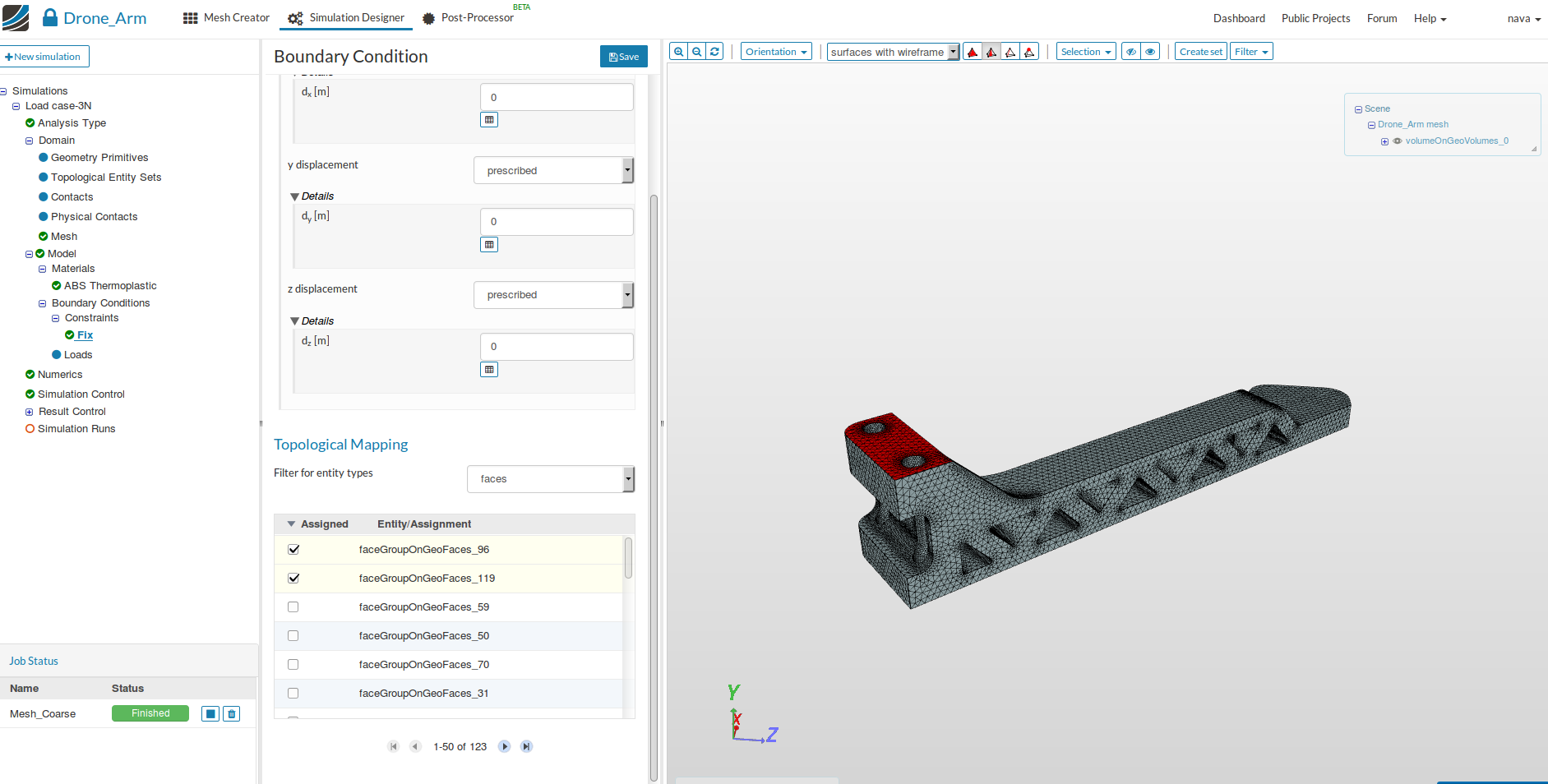
- First we will define a constraint boundary condition to fix the arm. Click therefore on the Constraint under Boundary Conditions in the tree.
- Click on New button

- Specify the following parameters:
- Name: Fix
- Type: Fixed Value
- dx[m]: 0
- dy[m]: 0
- dz[m]: 0
- Select faces for the option Fliter for entity types under Topological Mapping.
- Select the upper and lower surface of the arm mount (faceGroupOnGeoFace_96, faceGroupOnGeoFace_119) where we want to apply this boundary condition.
- Click on Add selection from viewer in the bottom to assign this boundary condition to the surface.
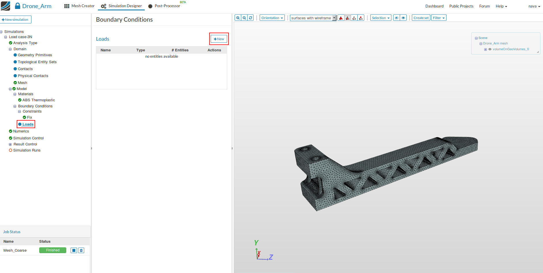
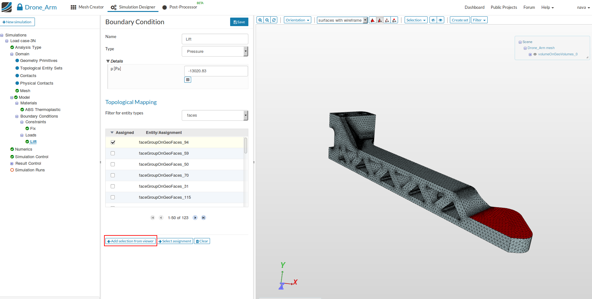
- Now, we will apply the lift created by the propeller on the arm. We therefore create load boundary condition by going to load under Boundary Conditions in the tree and then clicking on New button.
-
For the Static Analysis type there is no option for applying force on an area. Therefore, pressure is calculated by dividing force (3N) divided by area (2.304 x 10⁻⁴ m-2).
-
Specify the following parameters:
- Name: Lift
- Type: : Pressure
- p[Pa] : -13020.83 (lift pressure)
-
Finally choose the top surface of the engine mount and click on Add selection from viewer to assign this boundary condition to the surface.
In this tutorial we want to investigate the deformation of the arm for different lift forces. Therefore you can duplicate the set up and modify the load value for each load cases.
Numerics,Simulation Control and Result Control, which are the next items in the project tree, can be skipped since the default settings are fine.
Simulation Runs
- To start the simulation, click on the Simulation Runs item in the tree and click on the New button.
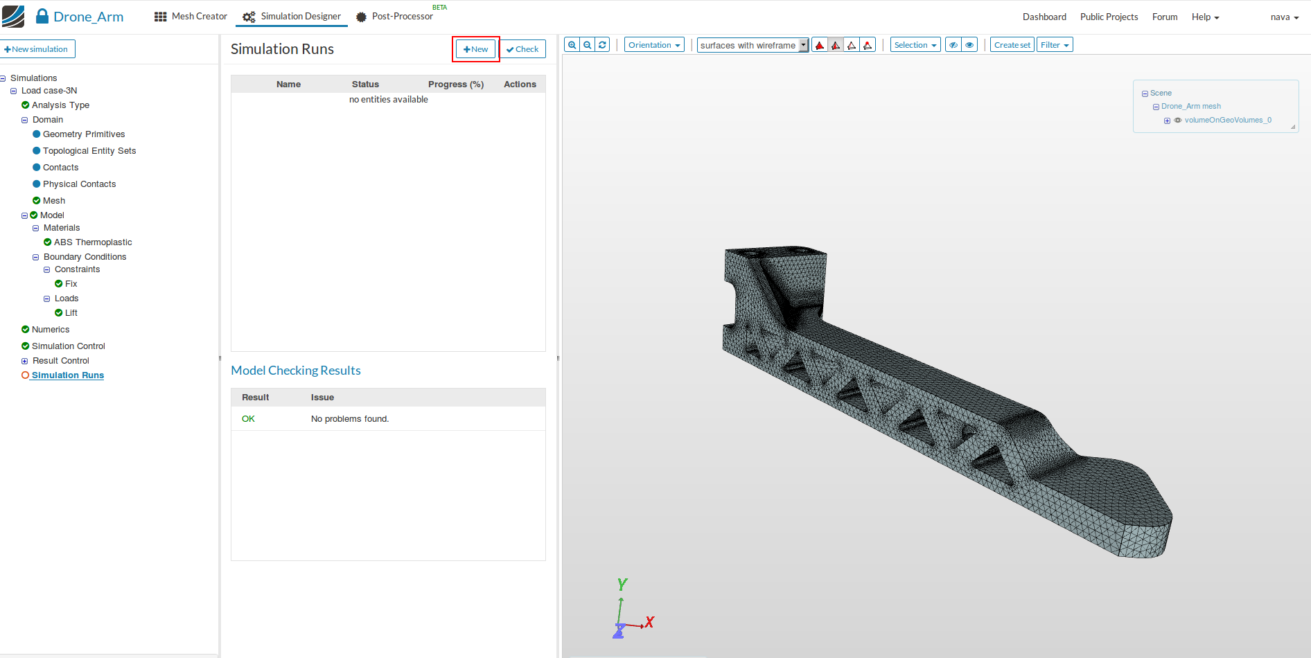
- This will create a snapshot of your simulation settings as a new sub-item.
- You can now start the simulation run by selecting it from the project tree and then click on the Start button.
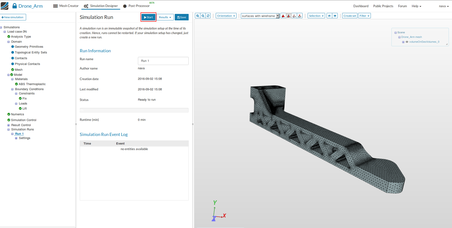
- Once your simulation is finished, you will see a Finished status in the lower left corner.
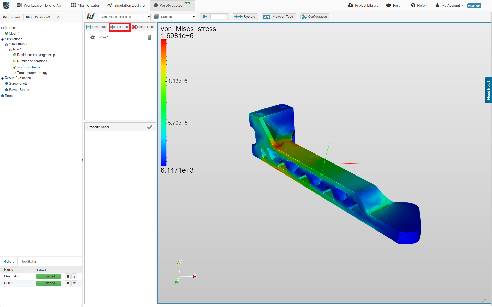
Post-Processing
- Click on Post-processing tab.
- Click on the Solution fields in the project tree to access the 3D simulation results.

We can also apply filters on our simulation result to get more insights.
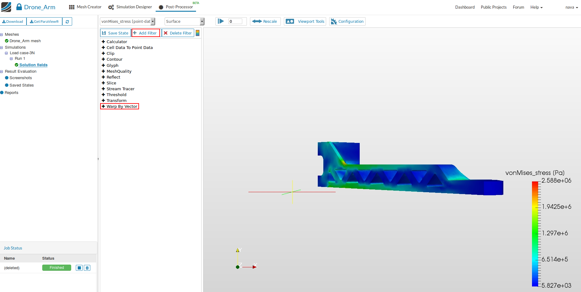
- First we will visualize the deformation of the arm using the Warp By Vector filter. Click therefore on the Add Filter button.
- Now you can choose the Wrap By Vector filter from the list
- In the Property panel you can define a scale factor for the displacement (20). Now you will be able to see the deformed and undeformed geometry and finally click on tick mark to apply the changes.
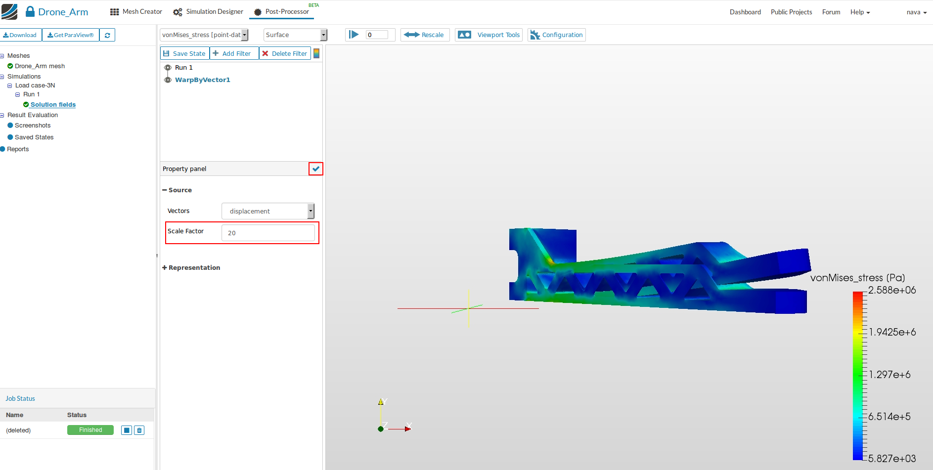
- To differentiate between the deformed and undeformed shape click on Run1 and then change the field to solid color and also change the opacity to 0.3 to make the undeformed result little transparent. Click on tick mark to apply the changes.
The final result looks like this.

Congratulations, you have completed the Homework of Session 2 - Level 1 and can now move on to the next level: