NOTE: This tutorial was updated on 08/2016 to match the updated version of the platform
If you would like to watch the third session of the Drone Workshop again or in the case you missed it, you can access the full recording below.
 - Drop Analysis of a Drone During Landing")
Exercise
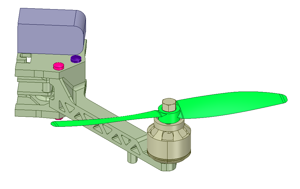
In this level of the homework we will set up a more realistic simulation of the drop test. We will therefore reduce the simplification of the model by using more components with different material properties.
We will investigate again four 4 fall velocities (1m/s, 2m/s, 5m/s, 10m/s)
Step-by-Step Instructions
Meshing
First of all you have to import the geometries into your SimScale workspace. For this you only have to click on this link and a project with everything you need will be added to your workspace. Please note that this can take several minutes.
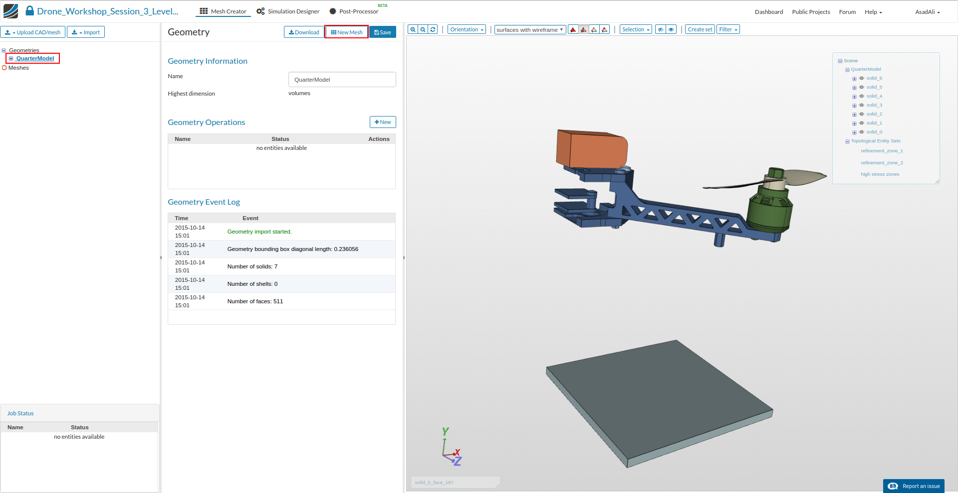
You will be notified when the project has been imported and it will be added to your project list on the left side. Once project is imported select the geometry QuarterModel and then click New Mesh to create mesh setup.
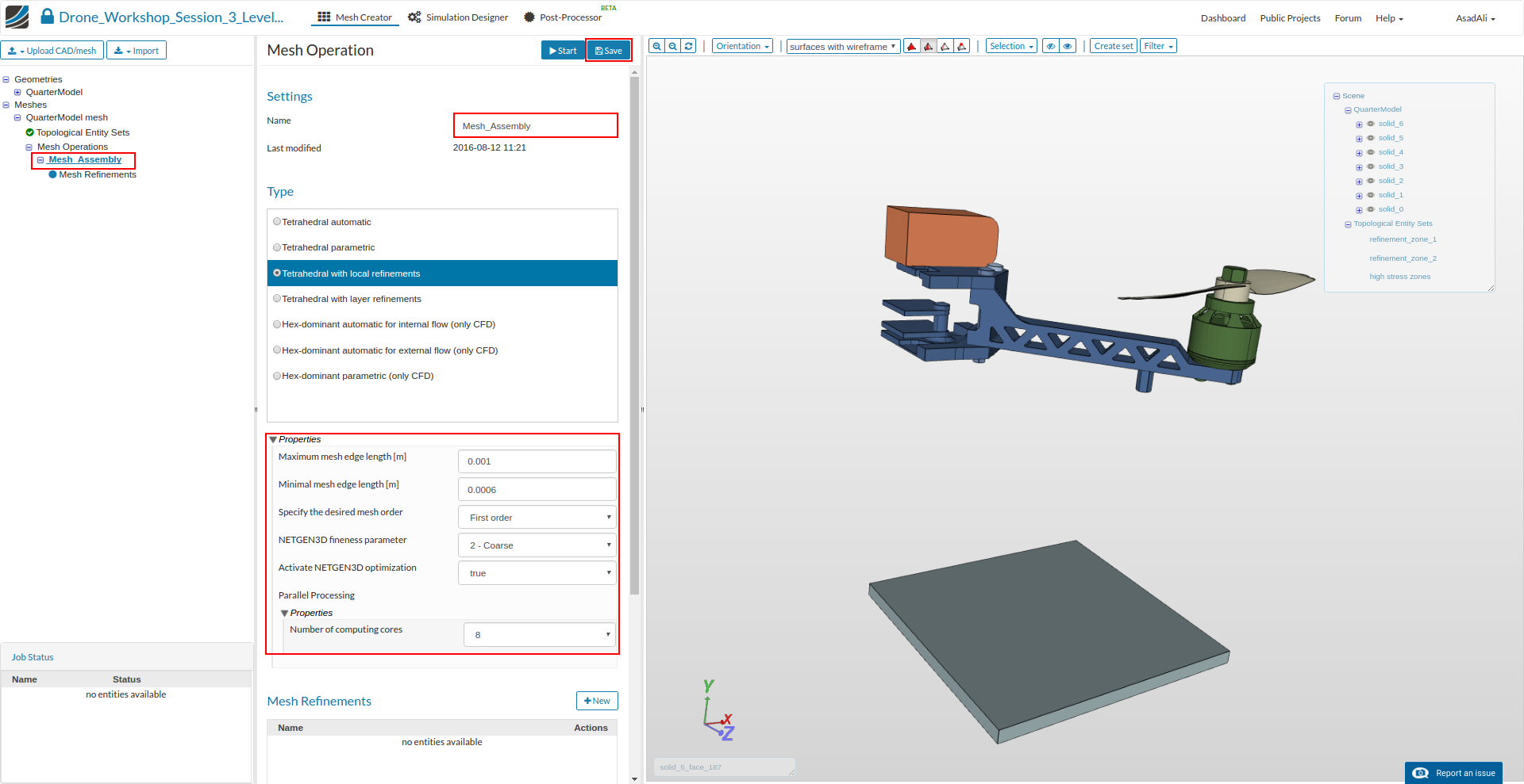
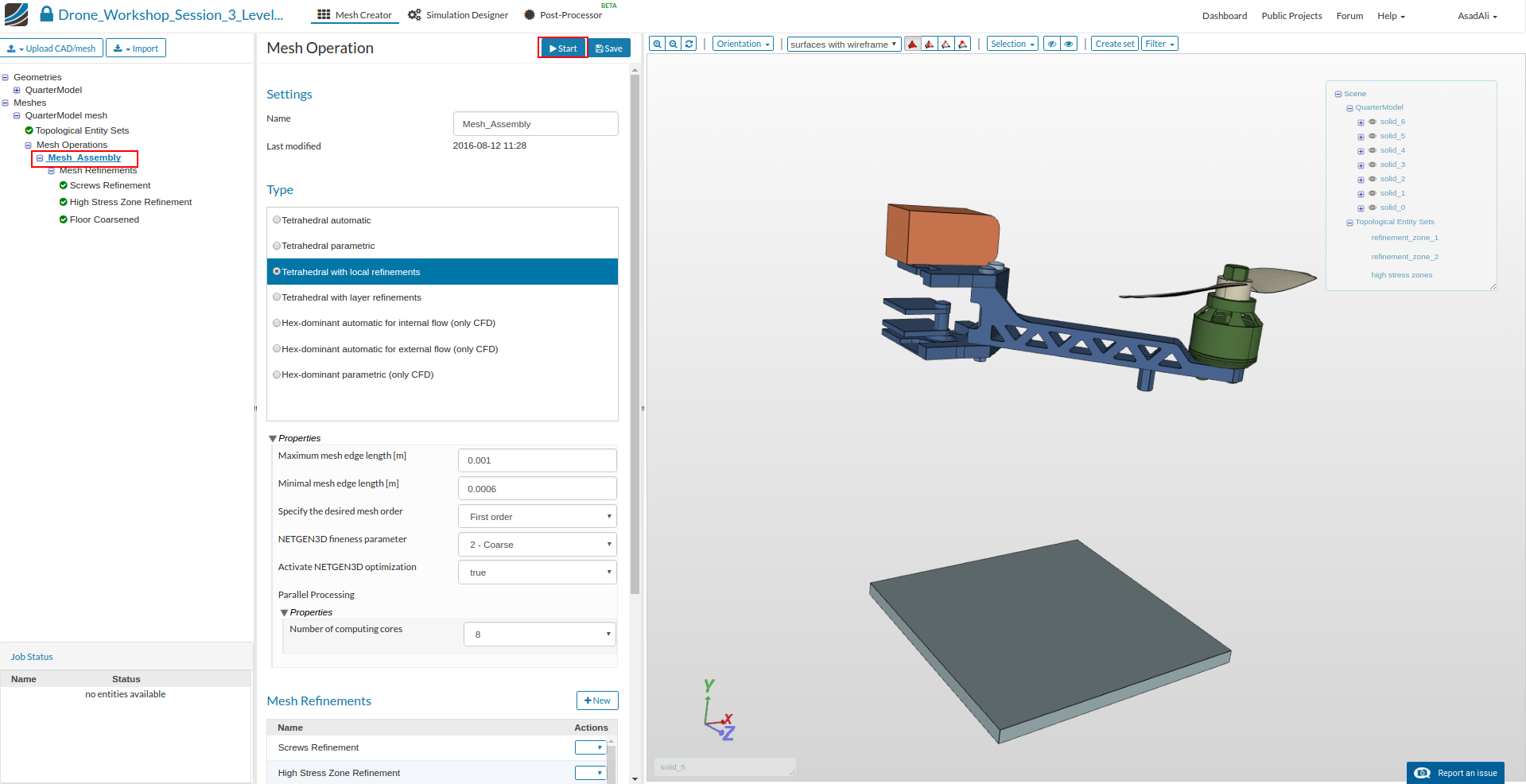
Next, click in mesh setup tree move to **** in Mesh operations. This will open a new middle menu where you can specify the mesh operation you want to use to create the mesh. Rename the mesh operation to Mesh.
Select ** Tetrahedral with local refinements** from the list and define following parameters:
- Name: Mesh_Assembly
- Maximum mesh edge length: 0.001
- Minimal mesh edge length: 0.0006
- NETGEN3D fineness parameter: 2 - Coarse
- Number of processors: 8
We now have defined a range for the base mesh size which is fine for regions where we are not expecting high stress. Here you should keep in mind that, in general, the mesh size is related to the local accuracy of the simulation. It is therefore necessary to refine the mesh in those areas where high stresses are expected.
We will now apply local refinements on two areas where we expect high stresses and high deformations and an additional local refinement to the floor to decrease the mesh resolution.
We will start with the two screws which connect the arm with the two base plates.
Click on the Mesh Refinements item which was added to the project tree. This will open again a menu in the middle column where all refinements are listed and where you can add new refinements.
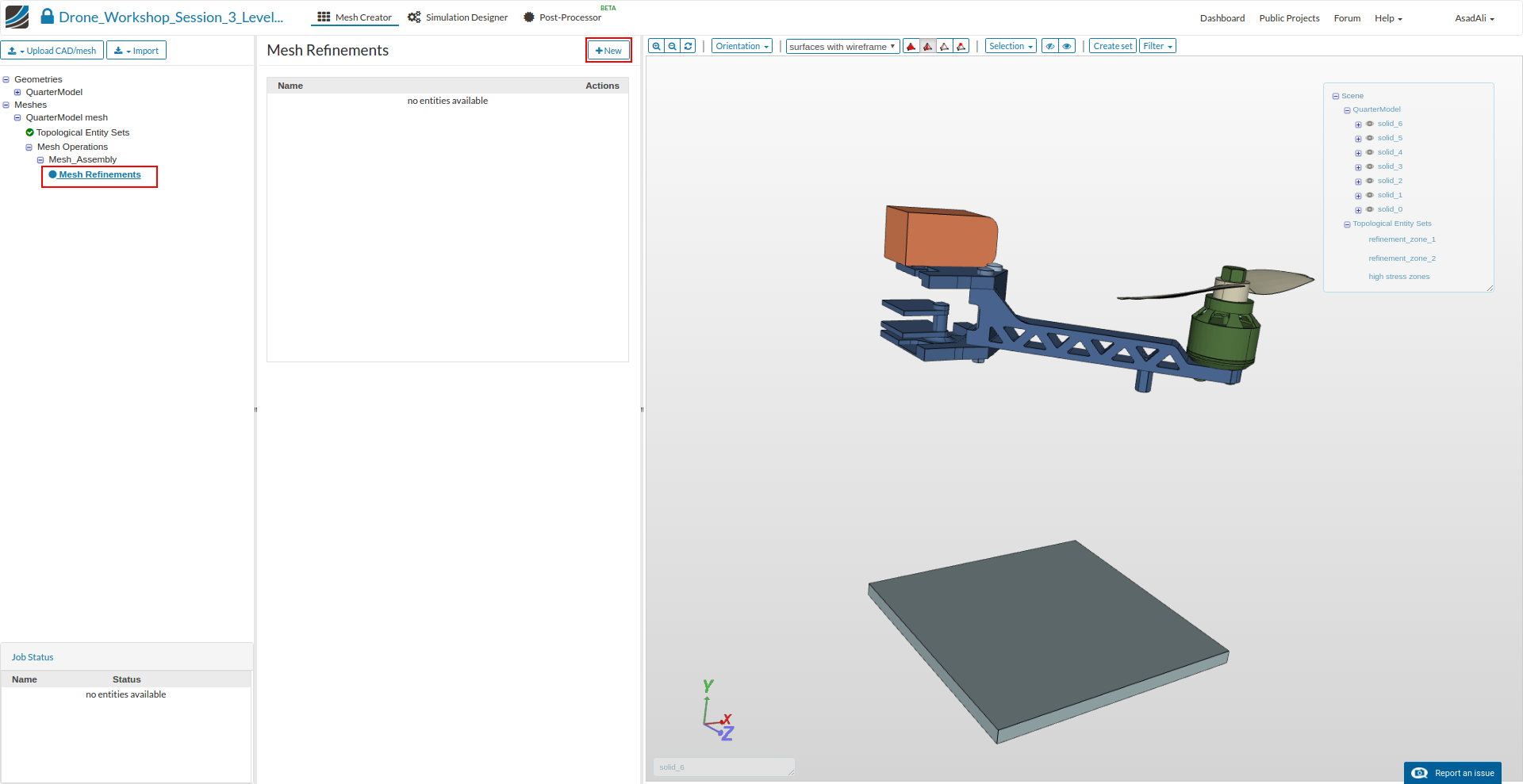
Click on the New button which will add a new sub-item to the project tree. Now you can specify the mesh refinement.
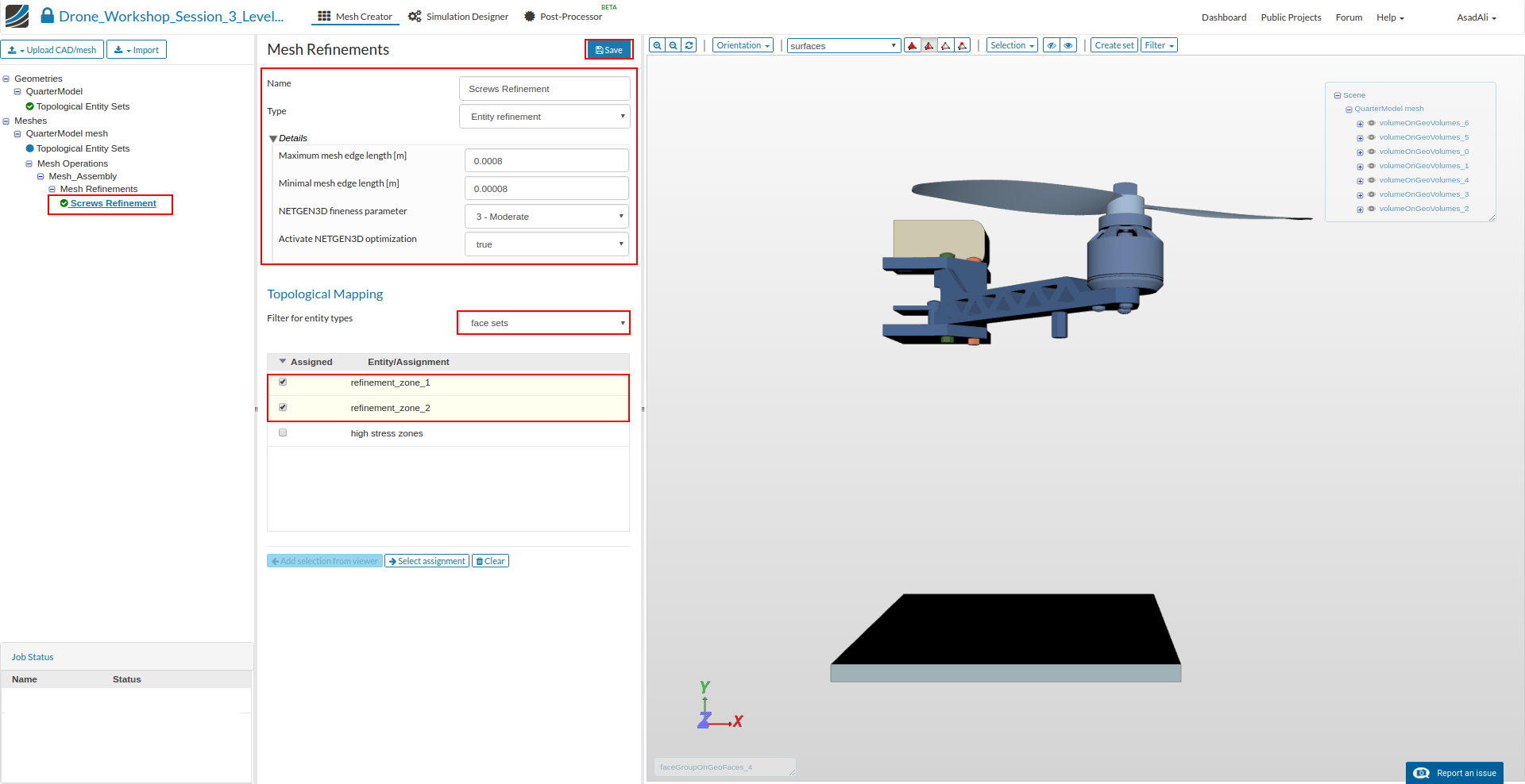
- Name: Screws Refinement
- Maximum mesh edge length: 0.0008
- Minimal mesh edge length: 0.00008
- NETGEN3D fineness parameter: 3 - Moderate
Next, select the faces you want to apply this refinement on by using the list below. Since the face selection would take a lot of time for this mesh we have prepared ready-to-use face sets. To use this sets, please change the Filter for entitiy type to face sets and select refinement_zone_1 and refinement_zone_2
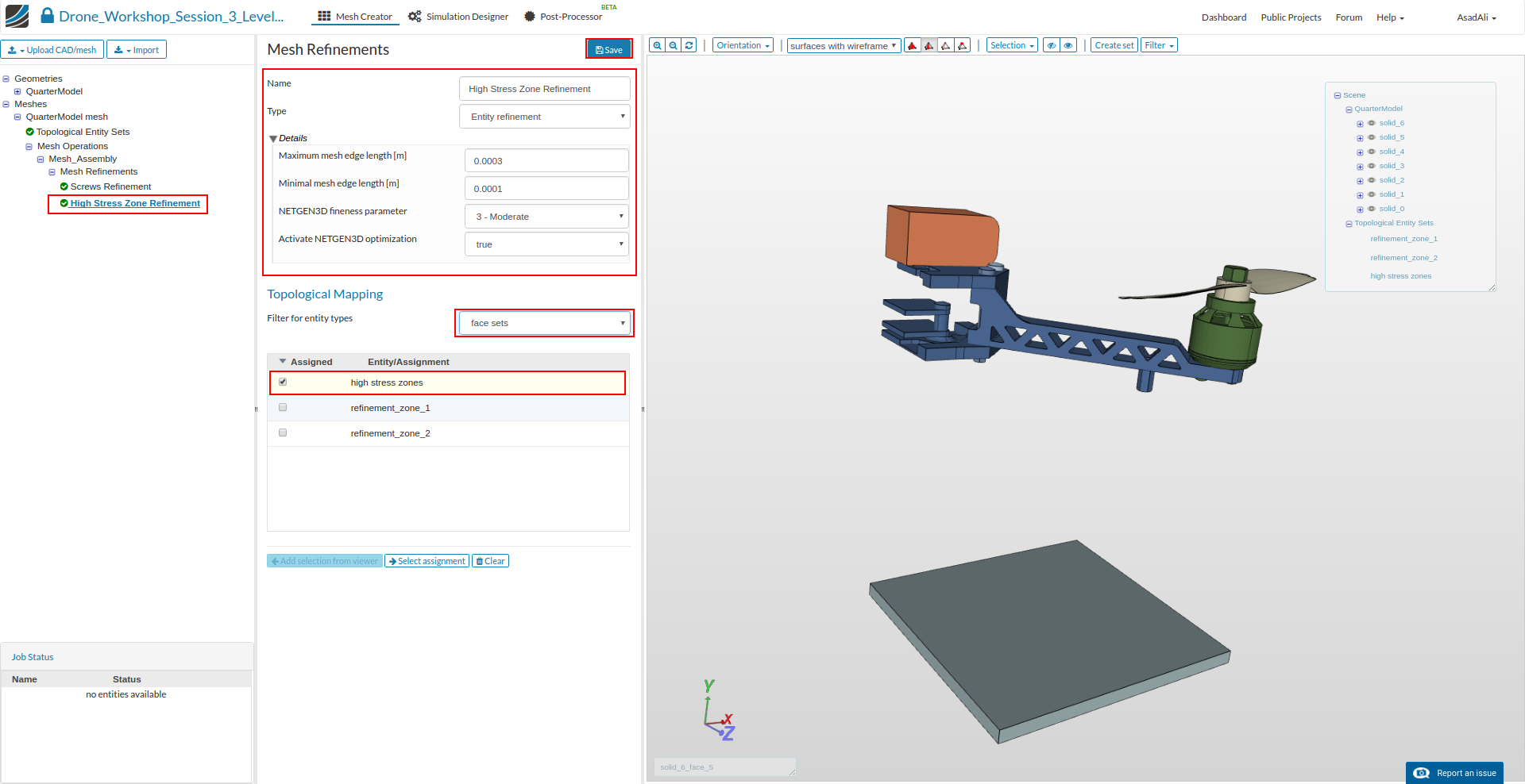
Create an additional mesh refinement by clicking on the New button which you will find again in the middle column when you click on the Mesh Refinements item in the project tree.

Now we will add refinement to some surfaces of the arms and the base plates. Specify the refinement as follows:
- Name: High Stress Zone Refinement
- Maximum mesh edge length: 0.0003
- Minimal mesh edge length: 0.0001
- NETGEN3D fineness parameter: 3 - Moderate
Next, assign this refinement to the face set which is called high stress zones
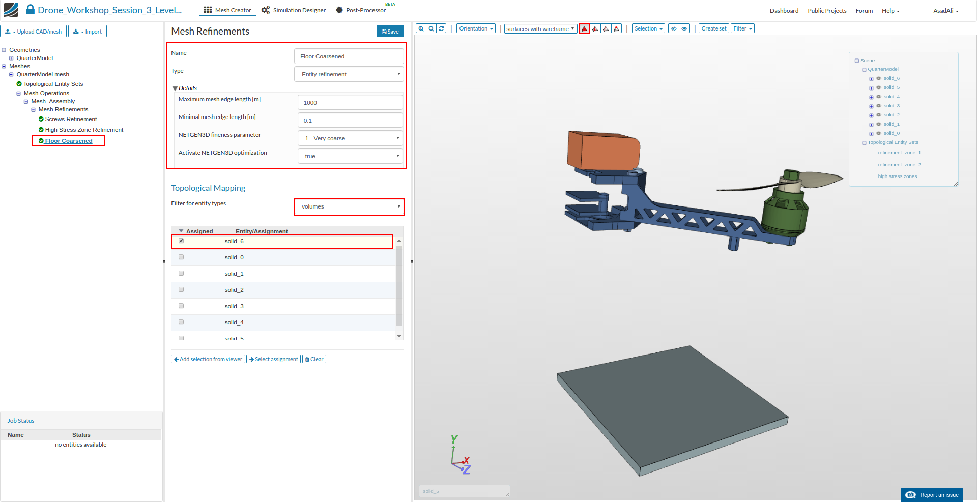
Finally, we will create a refinement which will coarsen the mesh of the floor. Specify the refinement as follows:
- Name: Floor Coarsened
- Maximum mesh edge length: 1000
- Minimal mesh edge length: 0.01
- NETGEN3D fineness parameter: 1 - Very coarse
Next, select the volumes of the floor (solid_6) by using the list below.
It is also possible and recommended to select the volumes which you want to assign to the boundary condition graphically.
You therefore have to change the selection mode to volume (1) select the volumes in the 3D model window on the left side by clicking on them with the left mouse button ; to add them to the list, just click on the Add selection from viewer button in the middle column.
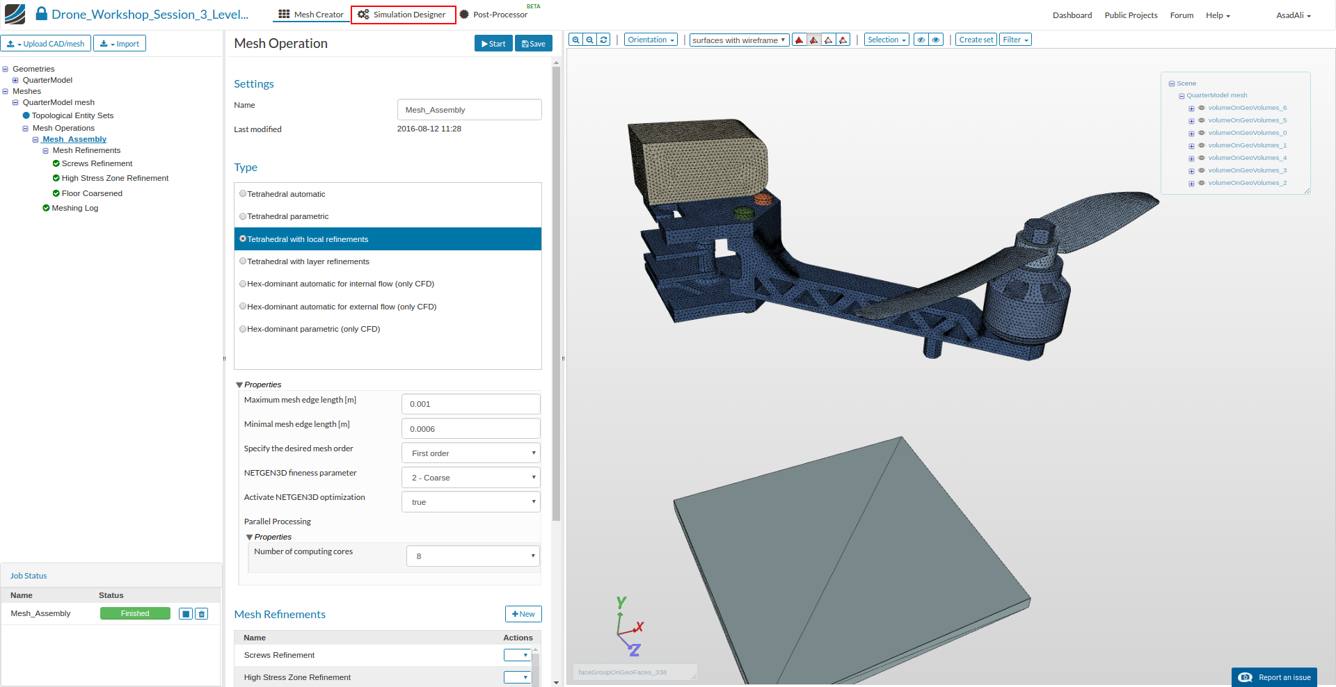
Now our mesh is ready for computation. Click on the meshing operation in the project tree and click the Start button.
Simulation Setup
After the mesh is completed we will set up the simulation. Click on the Simulation Designer button in the main ribbon bar.
Click on the New simulation button to create a simulation. Rename the simulation to “Drop_Test”
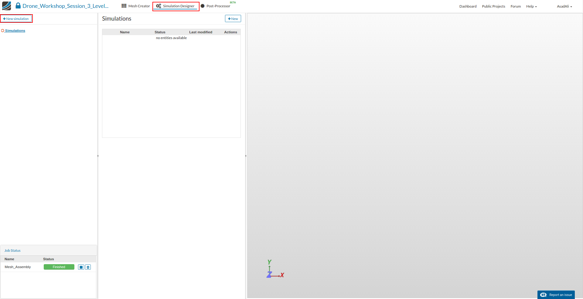
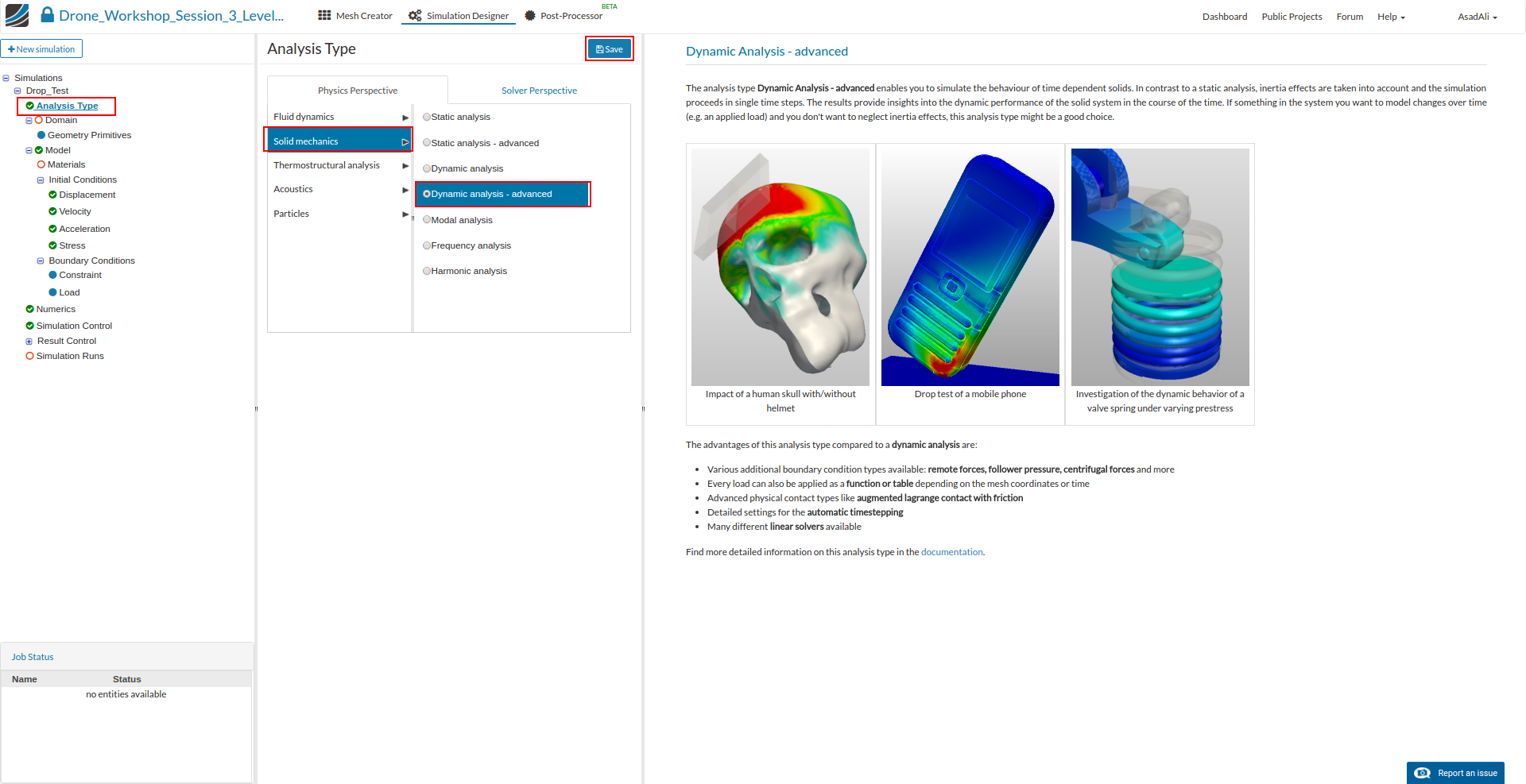
This will open an additional column in the middle. Here you can select what kind of simulation you want to run.
In our case we will run a Dynamic Analysis - advanced simulation.
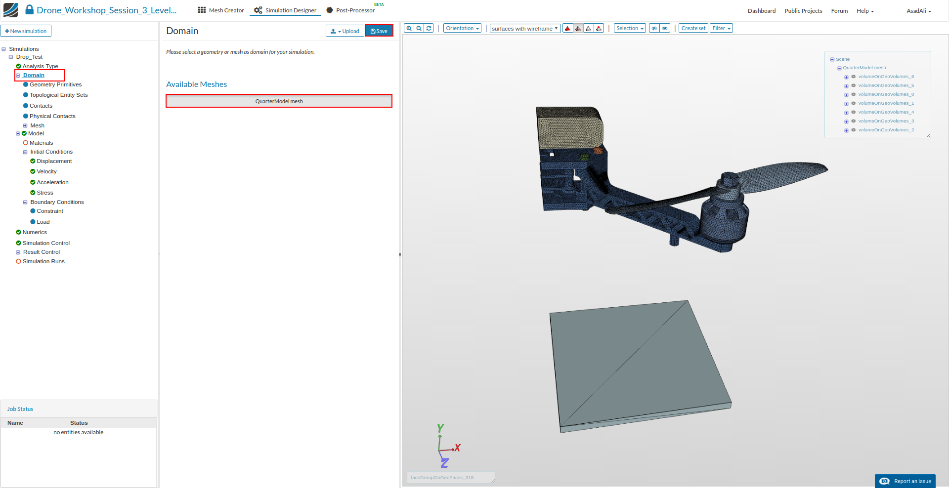
Next you have to specify which mesh you want to use for your simulation. Click on the Domain item in the project tree and select QuarterModel mesh from the menu which disappears in the middle column. Don’t forget to save your selection.
Since we are simulating an assembly of six parts, it is necessary to define Contacts which are describing the kinematic behavior of the parts.
Click on the Contacts item in the project tree which will open a new middle column menu where you can add new contacts by clicking on the related button.

Now we have to create four contacts which are connecting the parts. To select them graphically it may be necessary to hide some of the other parts.
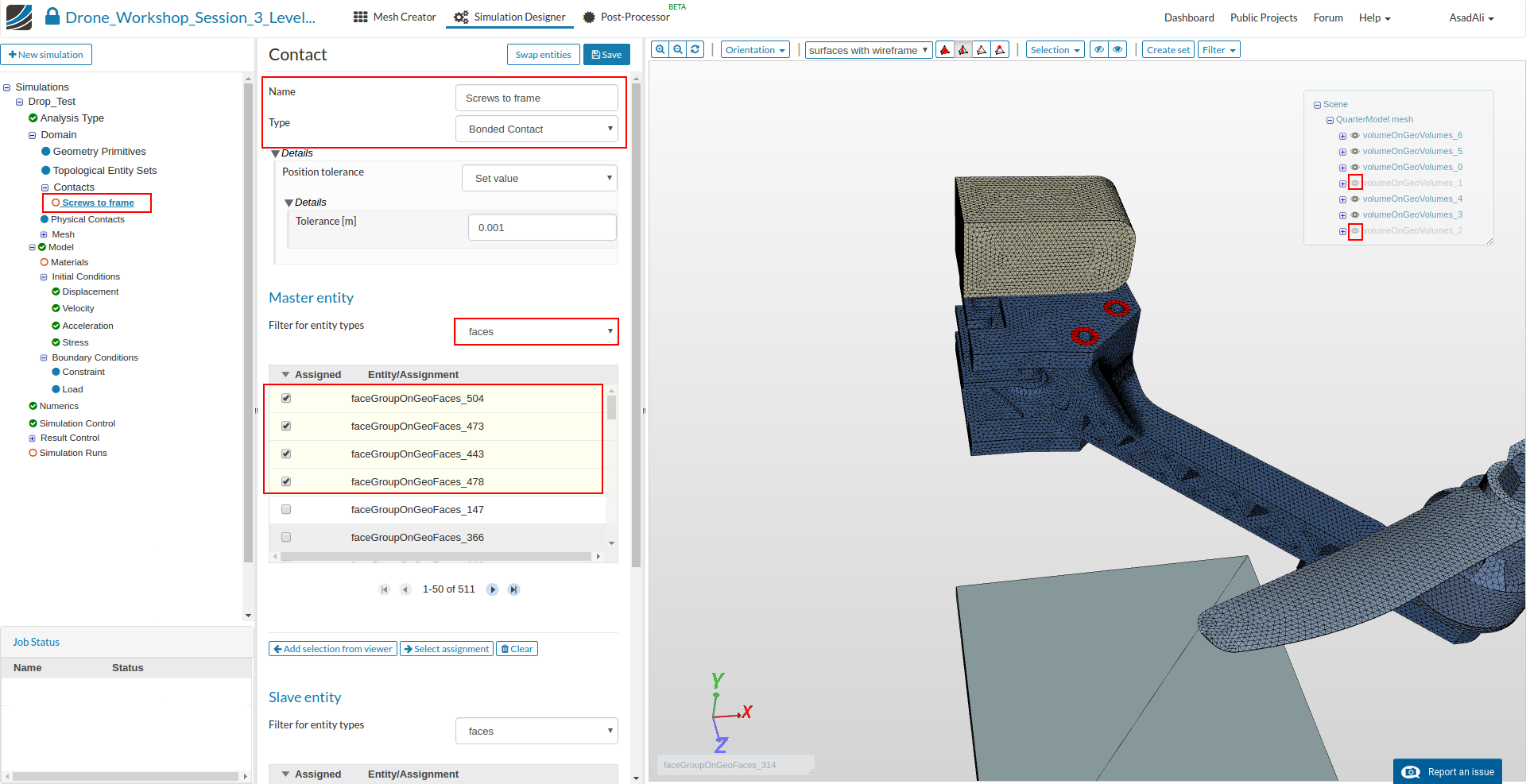
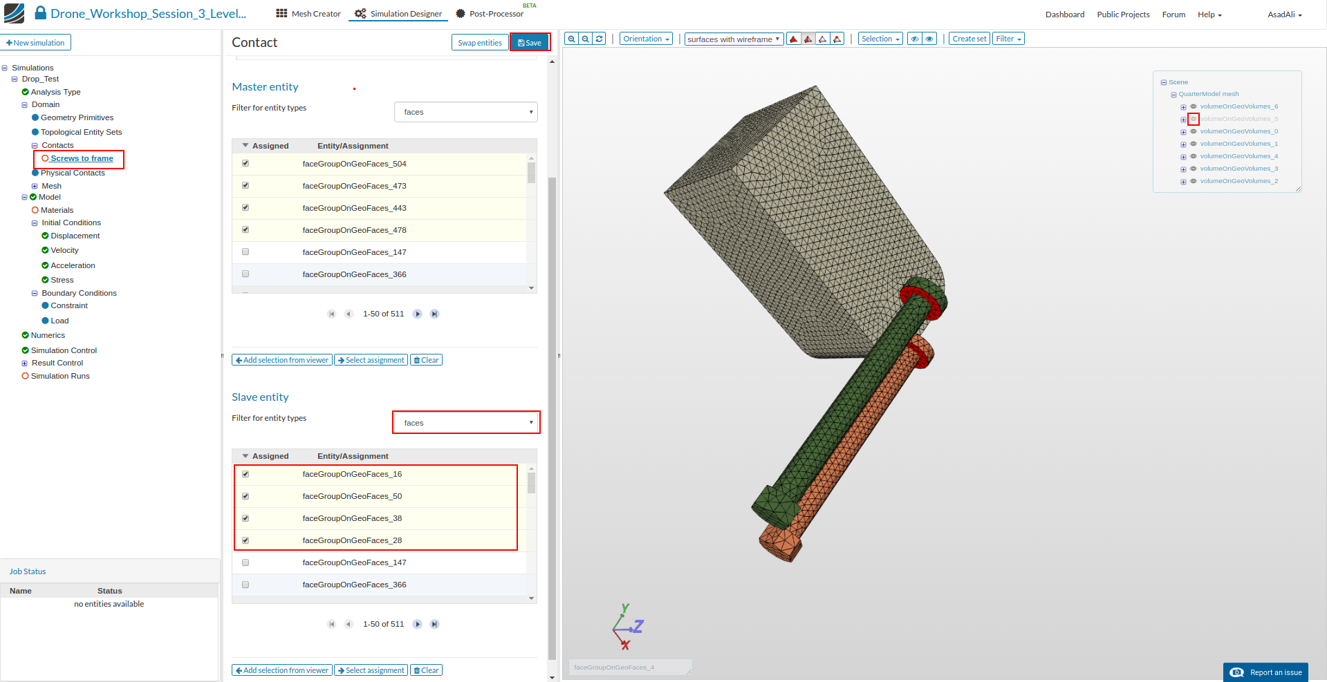
Screws to Frame
This contact is necessary to connect the two base plates through the screws. We will therefore define a contact between the contact area of the screw heads (slave) and the base plates (master).
- Name: Screws to frame
- Type: Bounded Contact
- Master entitiy: faceGroupOnGeoFaces_443, faceGroupOnGeoFaces_473, faceGroupOnGeoFaces_478, faceGroupOnGeoFaces_504
- Slave entity: faceGroupOnGeoFaces_16, faceGroupOnGeoFaces_28, faceGroupOnGeoFaces_38, faceGroupOnGeoFaces_50
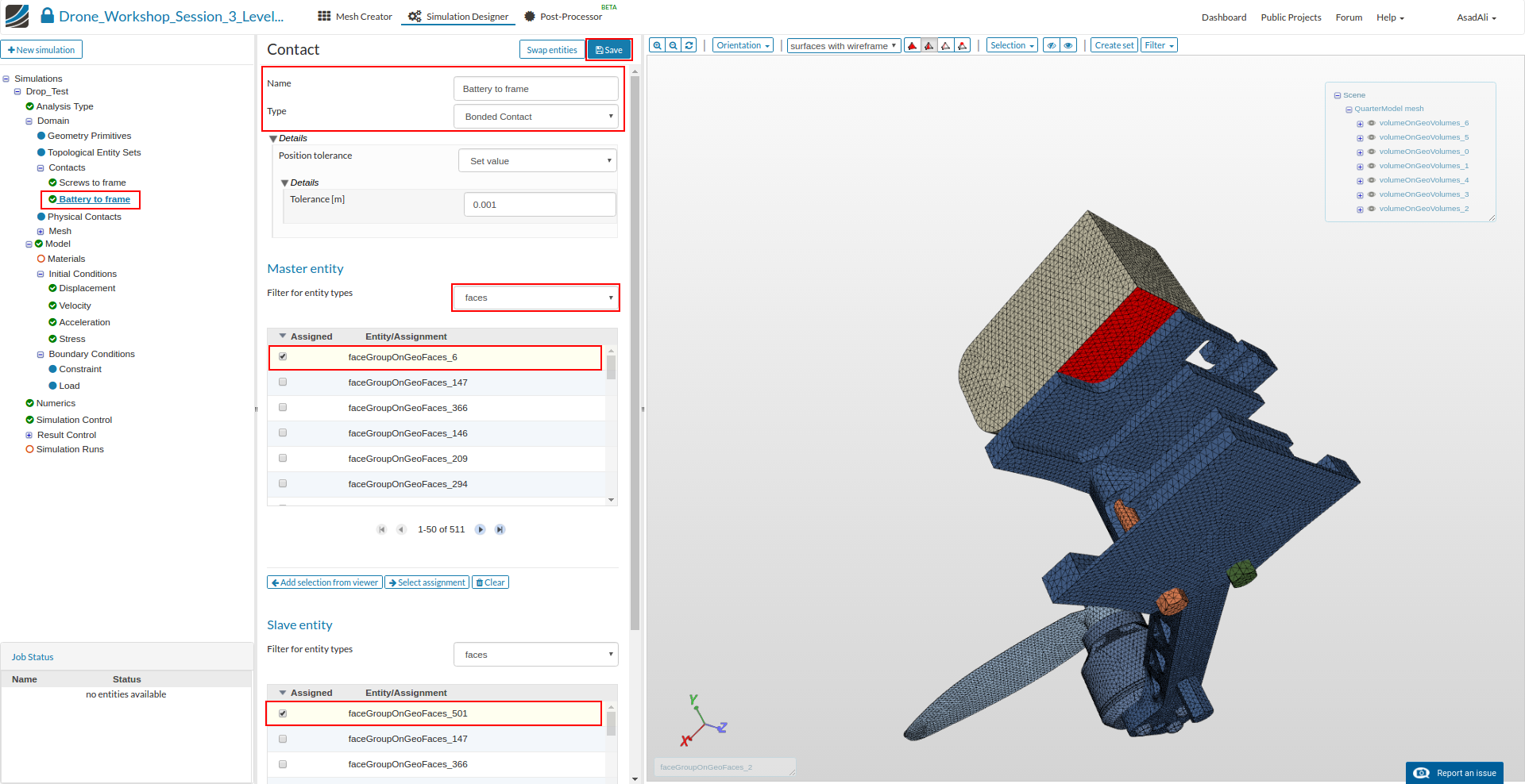
Battery to Frame
This contact is necessary to fix the battery on the upper base plate. We will therefore define a contact between the lower face of the battery (master) and the contact area between both parts on the base plate (slave).
- Name: Battery to Frame
- Type: Bounded Contact
- Master entitiy: faceGroupOnGeoFaces_6
- Slave entity: faceGroupOnGeoFaces_501
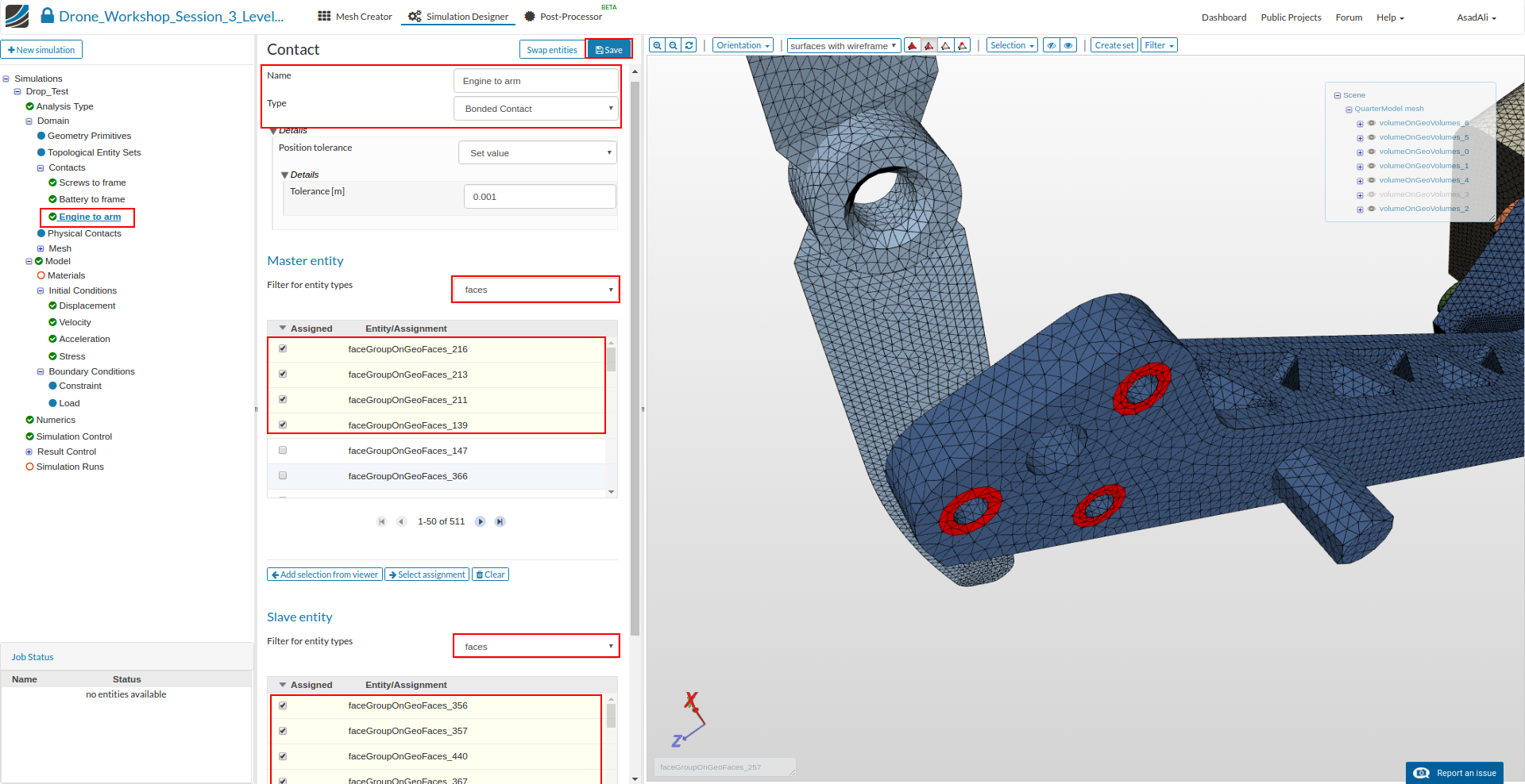
Engine to arm
This contact is necessary to fix the engine on the arm of the drone. We will therefore define a contact between the lower face of the engine, the arm and the screws.
- Name: Engine to arm
- Type: Bounded Contact
- Master entitiy: faceGroupOnGeoFaces_139, faceGroupOnGeoFaces_211, faceGroupOnGeoFaces_213, faceGroupOnGeoFaces_216
- Slave entity: faceGroupOnGeoFaces_356, faceGroupOnGeoFaces_357, faceGroupOnGeoFaces_367, faceGroupOnGeoFaces_440
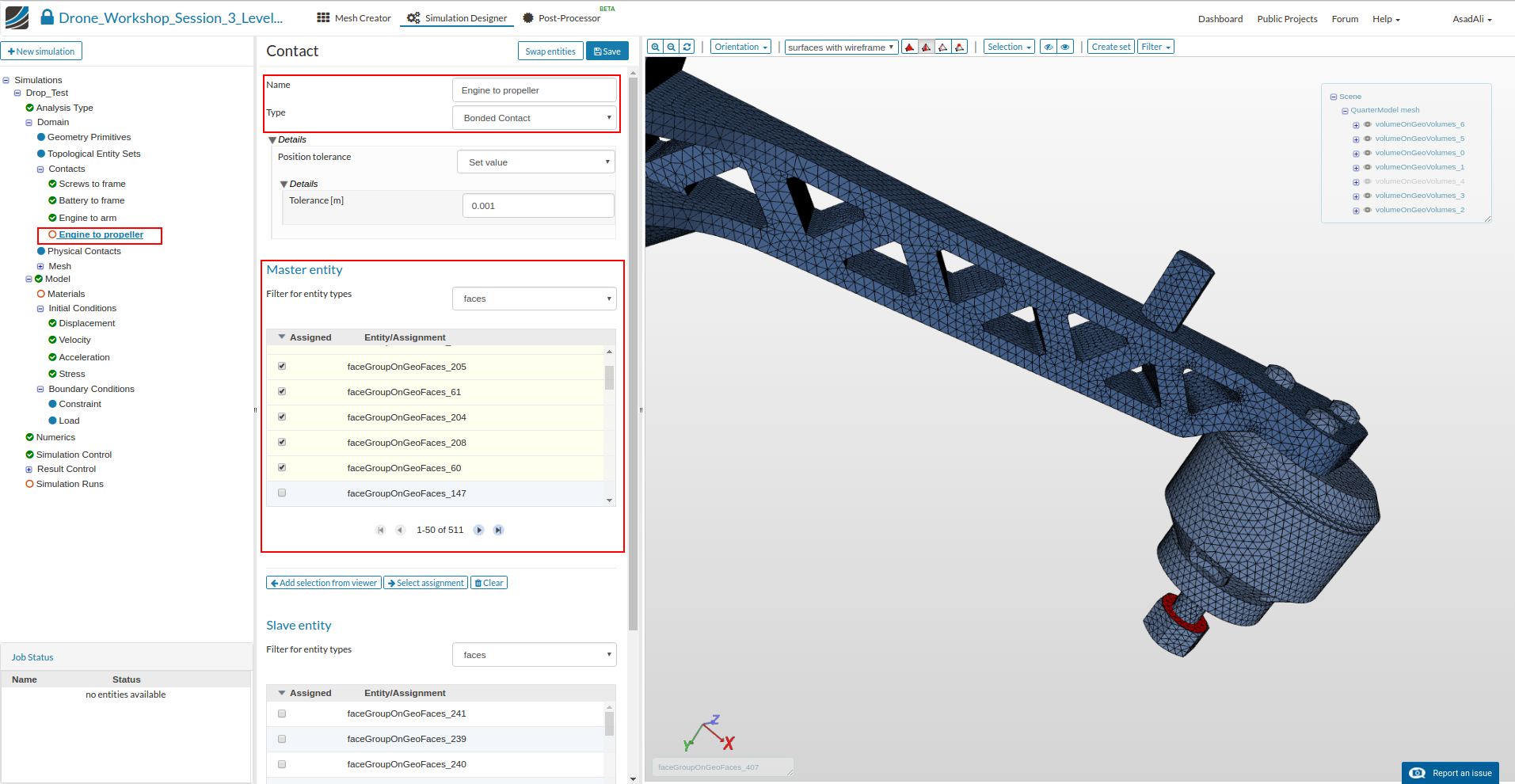
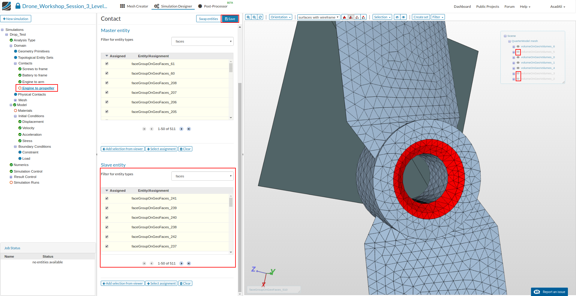
Engine to propeller
This contact is necesaary to fix the propeller on the drive shaft of the engine. Since this connection is based on a screw connection, we will define a contact area between the propeller (slave) and the engine (master).
- Name: Engine to propeller
- Type: Bounded Contact
- Master entitiy: faceGroupOnGeoFaces_60, faceGroupOnGeoFaces_61, faceGroupOnGeoFaces_126, faceGroupOnGeoFaces_127, faceGroupOnGeoFaces_182, faceGroupOnGeoFaces_204, faceGroupOnGeoFaces_205, faceGroupOnGeoFaces_206, faceGroupOnGeoFaces_207, faceGroupOnGeoFaces_208
- Slave entity: faceGroupOnGeoFaces_237, faceGroupOnGeoFaces_238, faceGroupOnGeoFaces_239, faceGroupOnGeoFaces_240, faceGroupOnGeoFaces_241, faceGroupOnGeoFaces_242
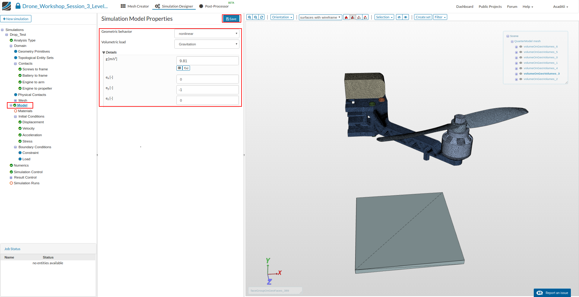
Next we have to define the physical Model we want to use for this simulation. Click on the Model item in the project tree which will open a middle column windows. Here you can define the Geometric behavior as well as gravity.
- Geometric behavior: nonlinear
- g: 9.81
- ex: 0
- ey: -1
- ez: 0
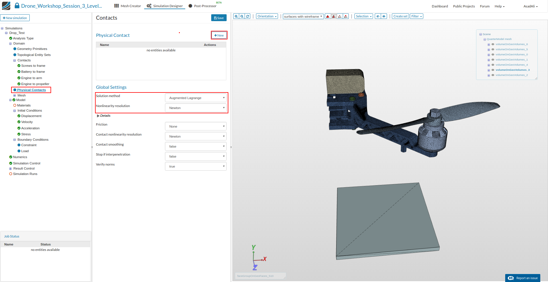
Next we will define the Physical Contacts. In contrast to Contacts, they are also covering the physical interaction between parts. We will use them to specify the contact between the dropping drone and the floor as well as the internal contact of the rotating and static part of the engine.
Click on the Physical Contacts item in the project tree. This will open a new middle column menu where we first will adapt two general settings:
- Solution method: Augmented Lagrange
- Nonlinearity resolution: Newton
Now we will create a new contact by clicking the New button.
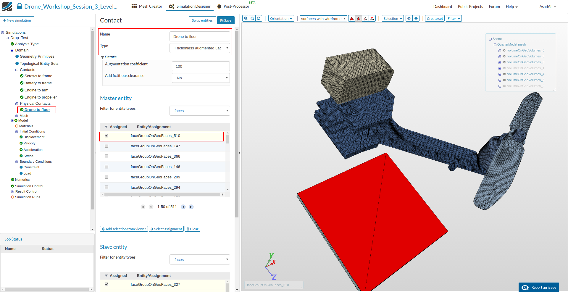
This will add a new contact to the project tree which you can edit by selecting the item from the tree.
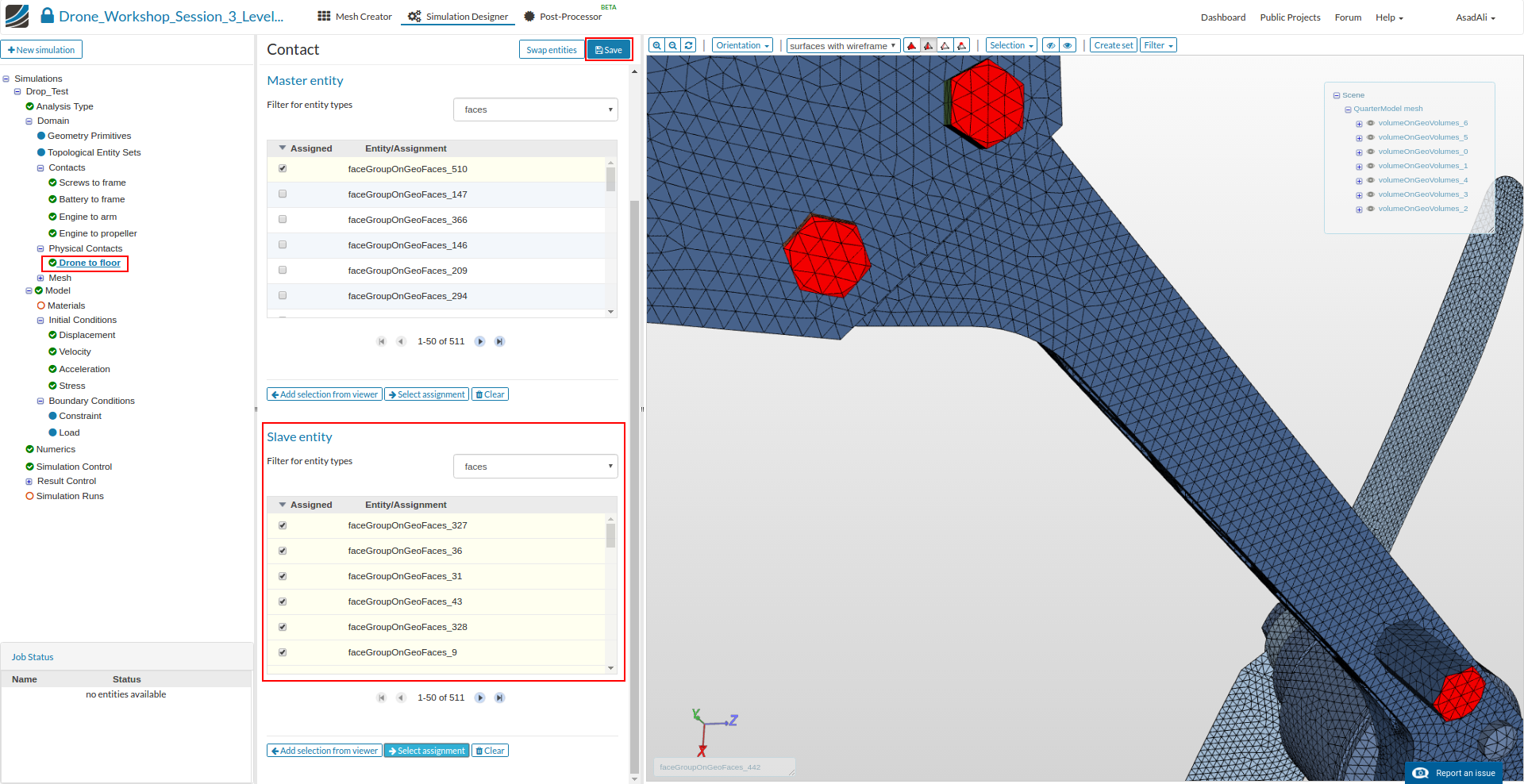
- Name: Drone to floor
- Type: Frictionless augmented lagrange
- Master entitiy: faceGroupOnGeoFaces_510
- Slave entity: faceGroupOnGeoFaces_8, faceGroupOnGeoFaces_9, faceGroupOnGeoFaces_14, faceGroupOnGeoFaces_15, faceGroupOnGeoFaces_17, faceGroupOnGeoFaces_18, faceGroupOnGeoFaces_19, faceGroupOnGeoFaces_20, faceGroupOnGeoFaces_21, faceGroupOnGeoFaces_30, faceGroupOnGeoFaces_31, faceGroupOnGeoFaces_36, faceGroupOnGeoFaces_37, faceGroupOnGeoFaces_39, faceGroupOnGeoFaces_40, faceGroupOnGeoFaces_41, faceGroupOnGeoFaces_42, faceGroupOnGeoFaces_43, faceGroupOnGeoFaces_320, faceGroupOnGeoFaces_323, faceGroupOnGeoFaces_324, faceGroupOnGeoFaces_325, faceGroupOnGeoFaces_326, faceGroupOnGeoFaces_327, faceGroupOnGeoFaces_328
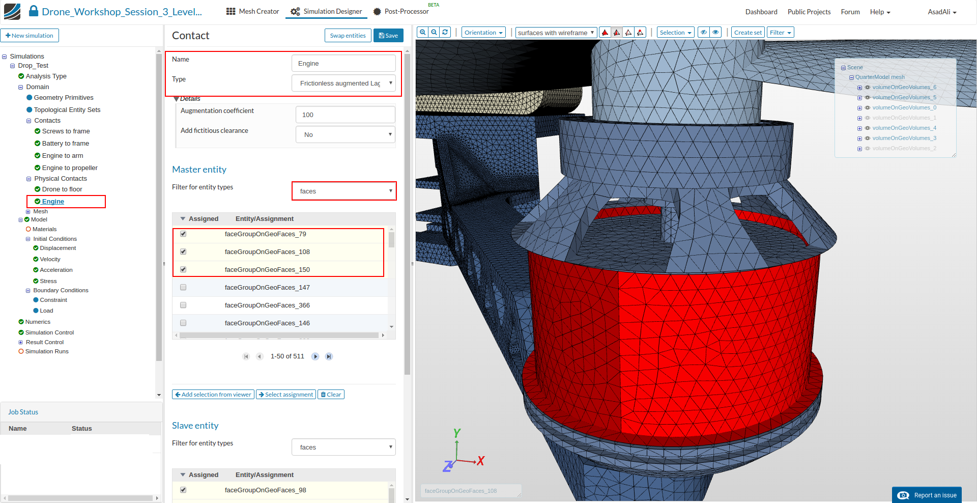
Next we will define a contact within the engine. Since the engine is made out of two parts (the static case and the rotating inner part), it is possible that the drop causes contact between the two parts.
Now add a new contact to the project and define it as follows. Please not that for graphical selection it is necessary to hide the outer faces of the engine.
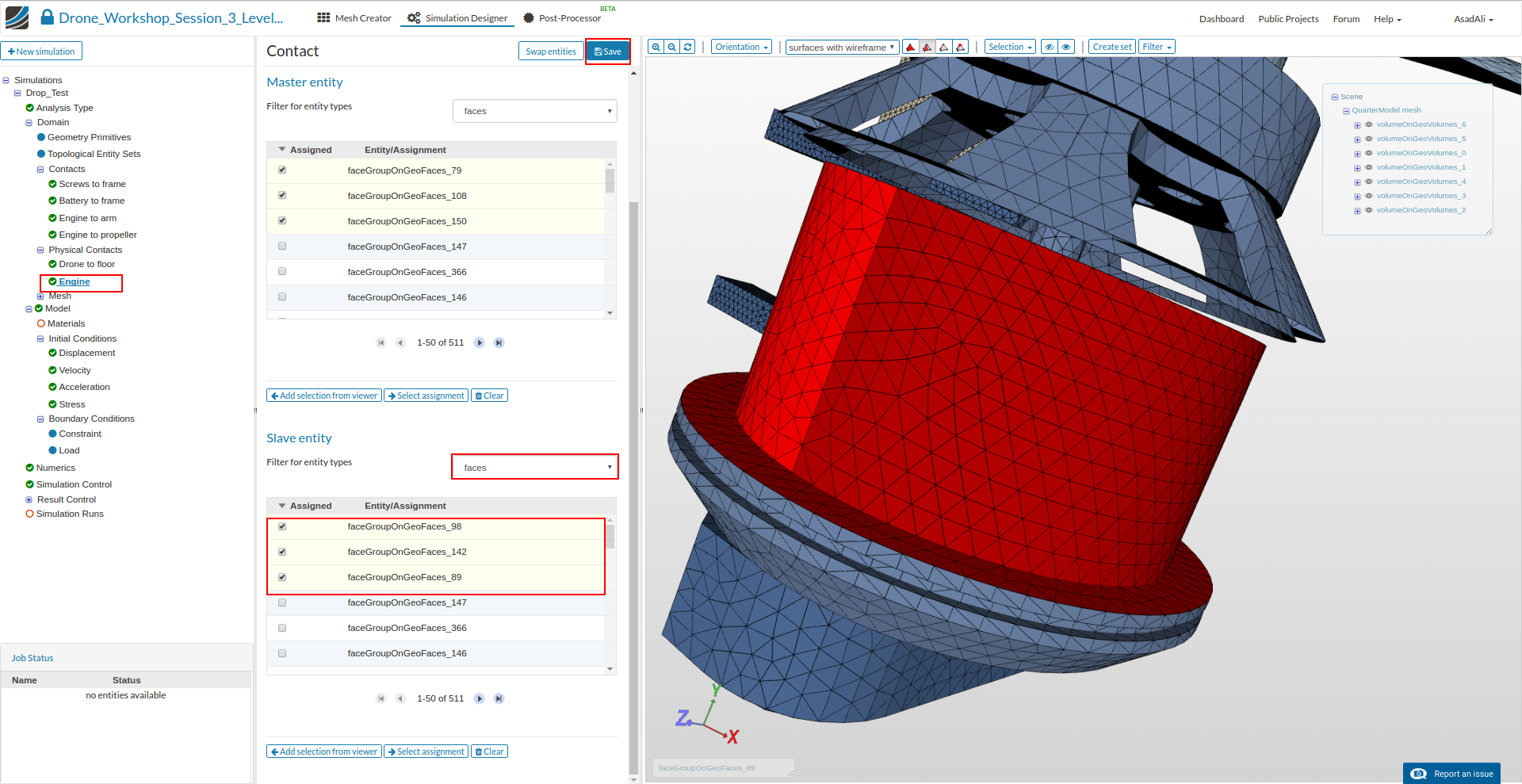
- Name: Engine
- Type: Frictionless augmented Lagrange
- Master entitiy: faceGroupOnGeoFaces_79, faceGroupOnGeoFaces_108, faceGroupOnGeoFaces_150
- Slave entity: faceGroupOnGeoFaces_89, faceGroupOnGeoFaces_98, faceGroupOnGeoFaces_142
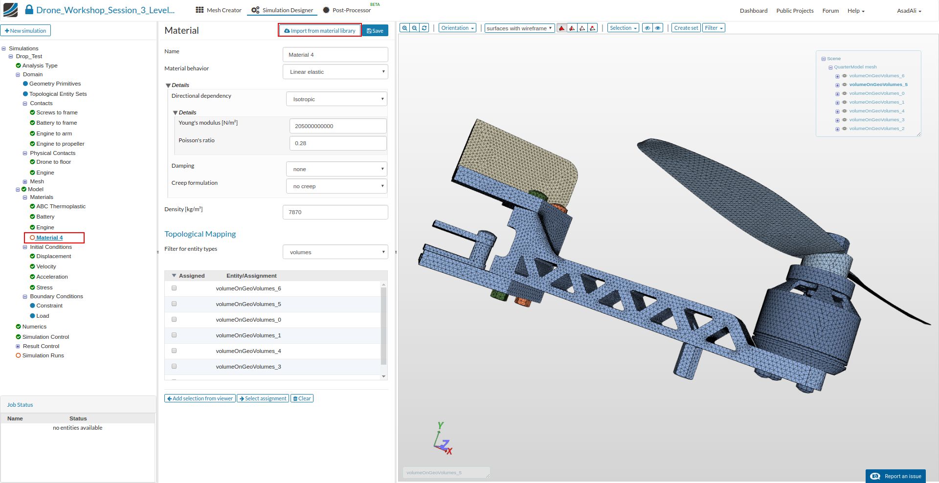
Now we define and assign material properties to the different parts. Click on the Material item in the project tree. This will open a middle column menu where you can edit and create materials and assign them to volumes. Click on the New button.
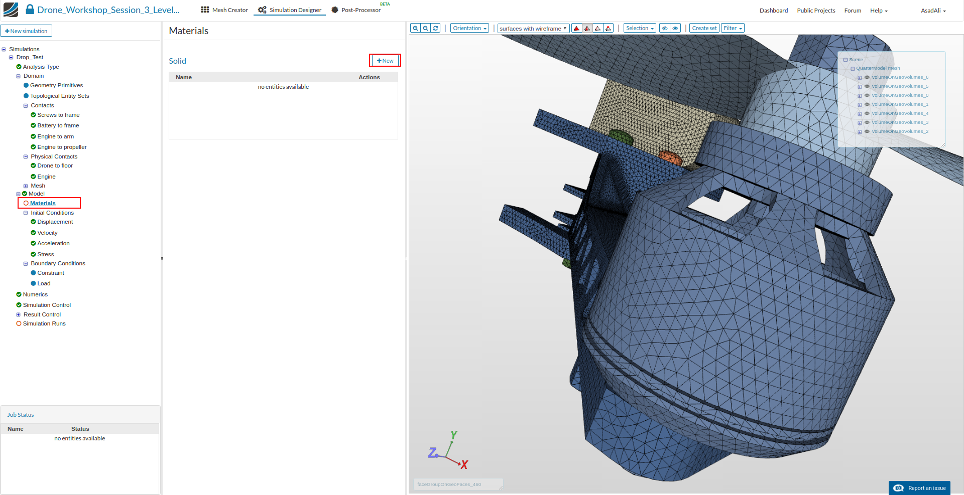
Now you can define your new material based on your own material proporties or access our Material Library which includes ready-to-use material models.
We will start with the manual definition of materials:
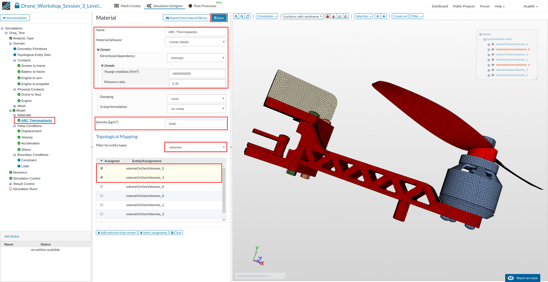
ABS Thermoplatics
- Name: ABS Thermoplastic
- Young’s Modul: 1800000000
- Poisson’s ratio: 0.35
- Densiy: 1040
And assign in to the drone frame (except the screws) and the propeller (volumeOnGeoVolumes_4, volumeOnGeoVolumes_5).
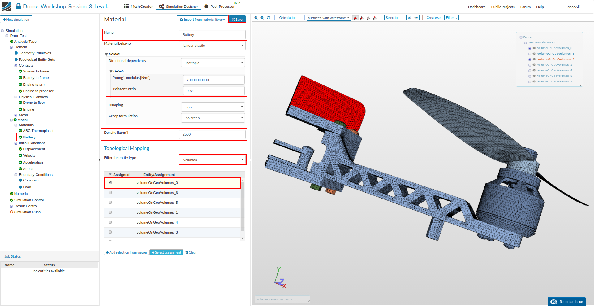
Add an additional material to your project tree.
Battery
- Name: Battery
- Young’s Modul: 70000000000
- Poisson’s ratio: 0.34
- Densiy: 2500
Assign the material to the battery of the drone (volumeOnGeoVolumes_0).
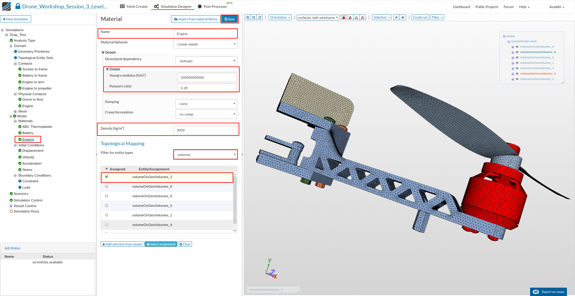
Add an additional material to your project tree.
Engine
- Name: Engine
- Young’s Modul: 205000000000
- Poisson’s ratio: 0.28
- Densiy: 3000
Assign the material to the engine (volueOnGeoVolumes_3)
Steel
Next we will assign the steel material model to the screw connections and the floor. Add an additional material to your project tree.
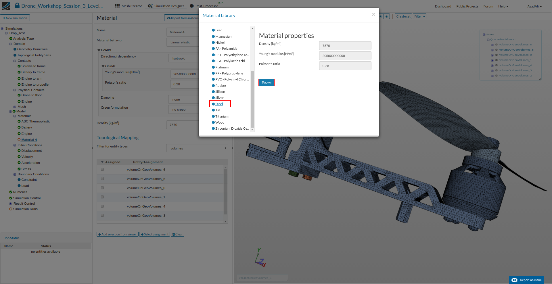
Now we will access our material library instead of creating the material model manually. Click on Import from material library which will open a widget.
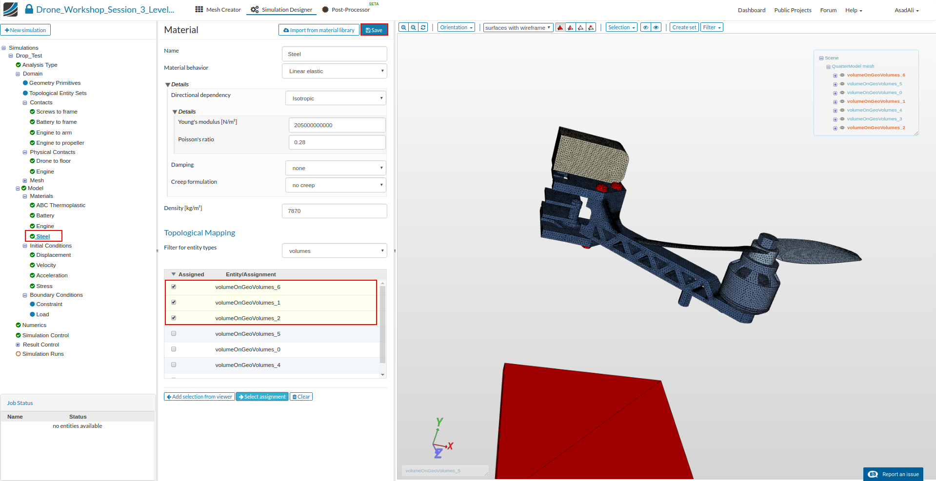
Please select steel from the list on the left side and save your selection by clicking the relevant button.
Now assign the material to the two screw connections and the floor (volumeOnGeoVolumes_1, volumeOnGeoVolumes_2, volumeOnGeoVolumes_6).
Since all kinematical and mechanical relations were defined, we will now take care for the interaction of our model with its environment.
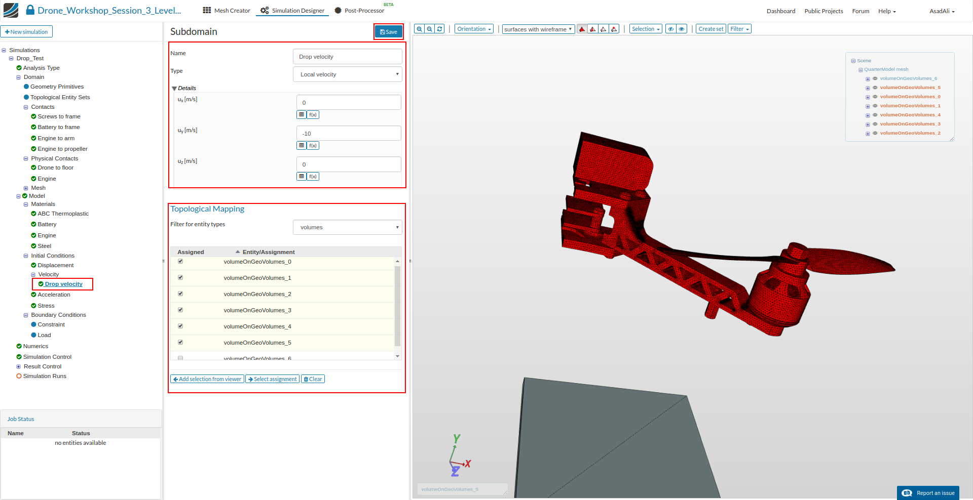
Click on velocity which is a sub-item of the Initial conditions in the project tree. This will open a new middle column window where you can define the initial values of velocity.
Since we only want to define the falling velocity of the drone (shortly before touching the floor), it is necessary to change the type for this initial condition to Subdomain-based.After saving this modification (1) , we are able to create a subdomain by clicking on New button (2).
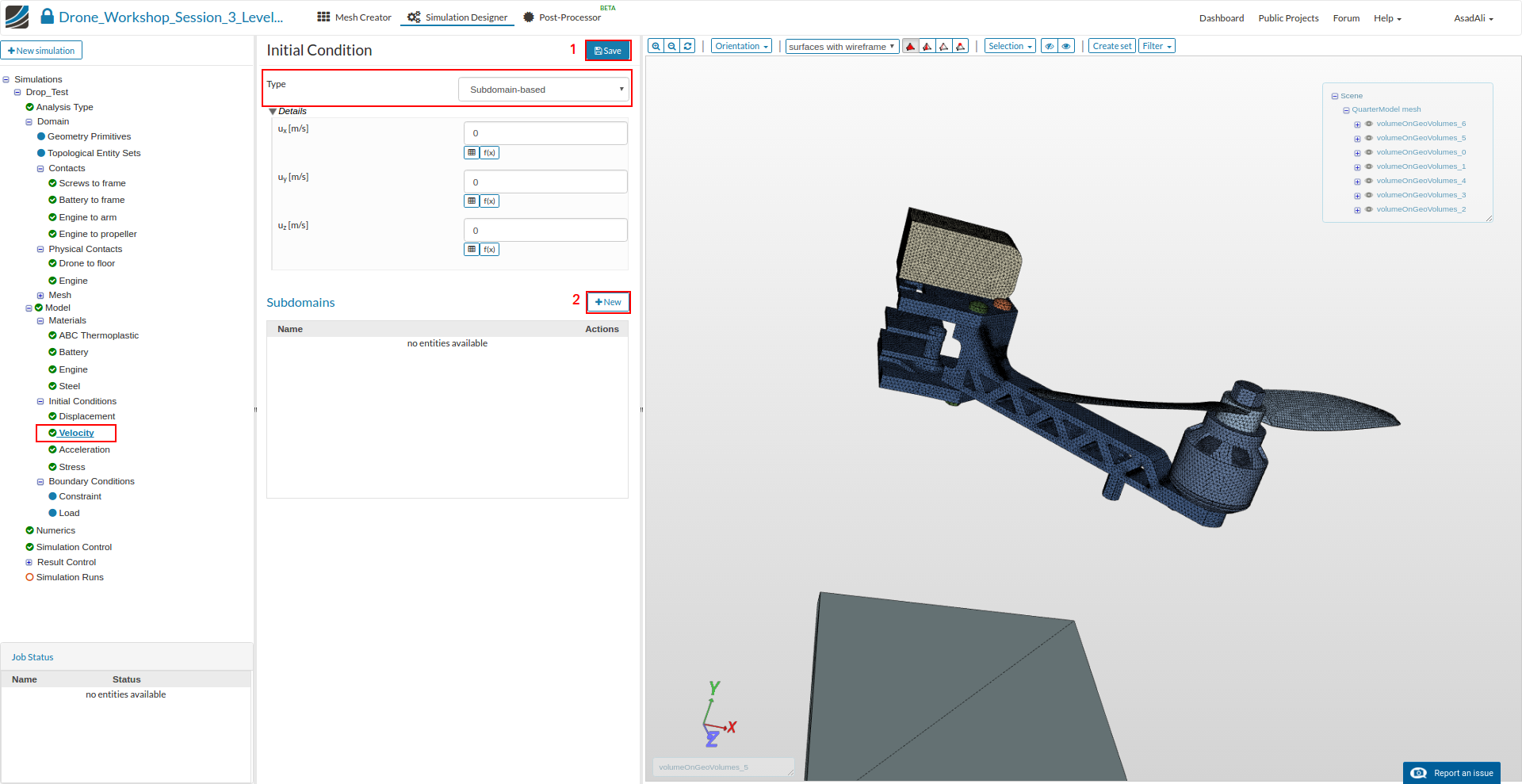
This will open a new middle column window where you have to define the following settings:
- Name: Drop Velocity
- ux: 0
- uy: -10
- uz: 0
Then map this condition to all volumes except the not moving floor (volumesOnGoVolumes_0, volumesOnGoVolumes_1, volumesOnGoVolumes_2, volumesOnGoVolumes_3, volumesOnGoVolumes_4, volumesOnGoVolumes_5)
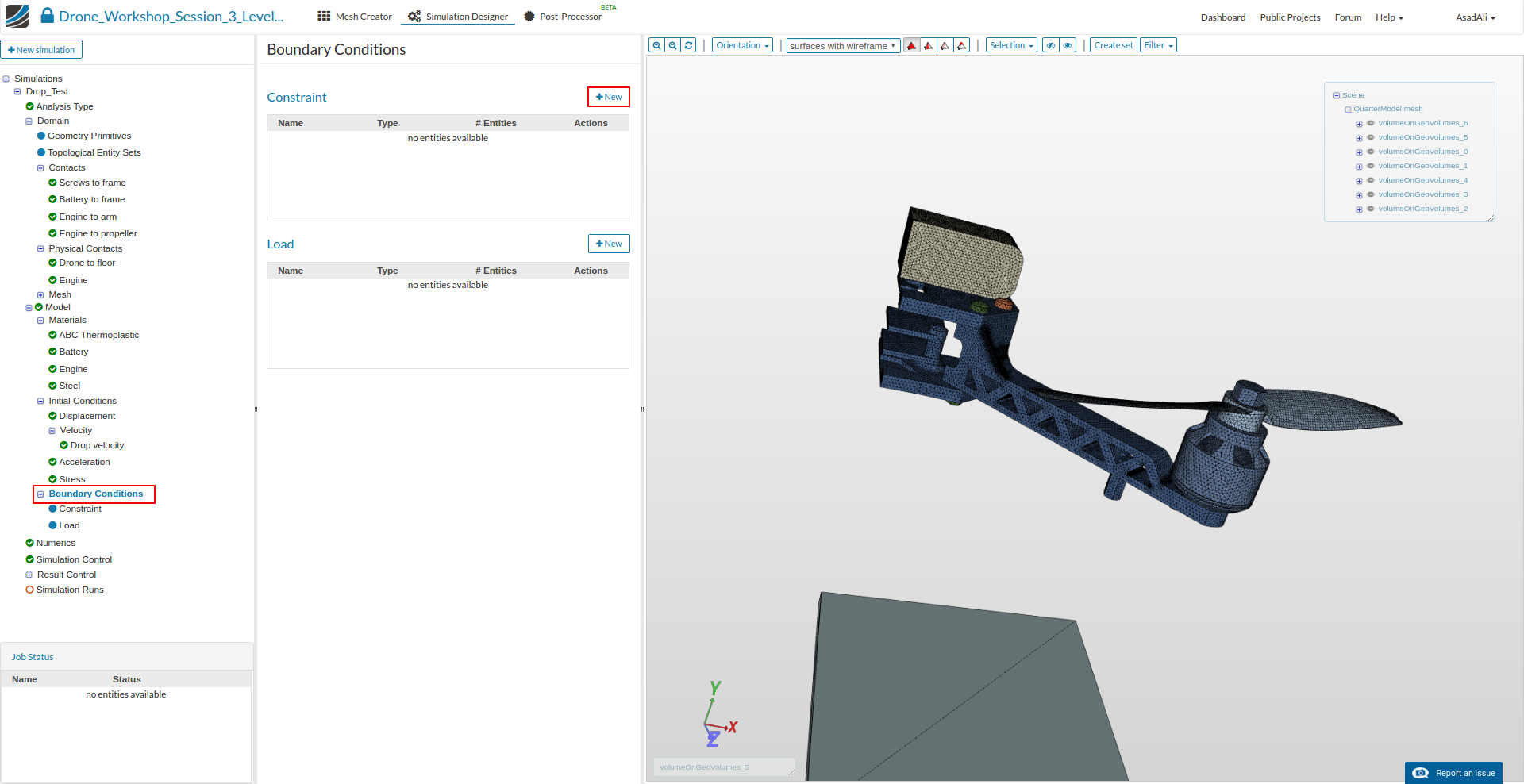
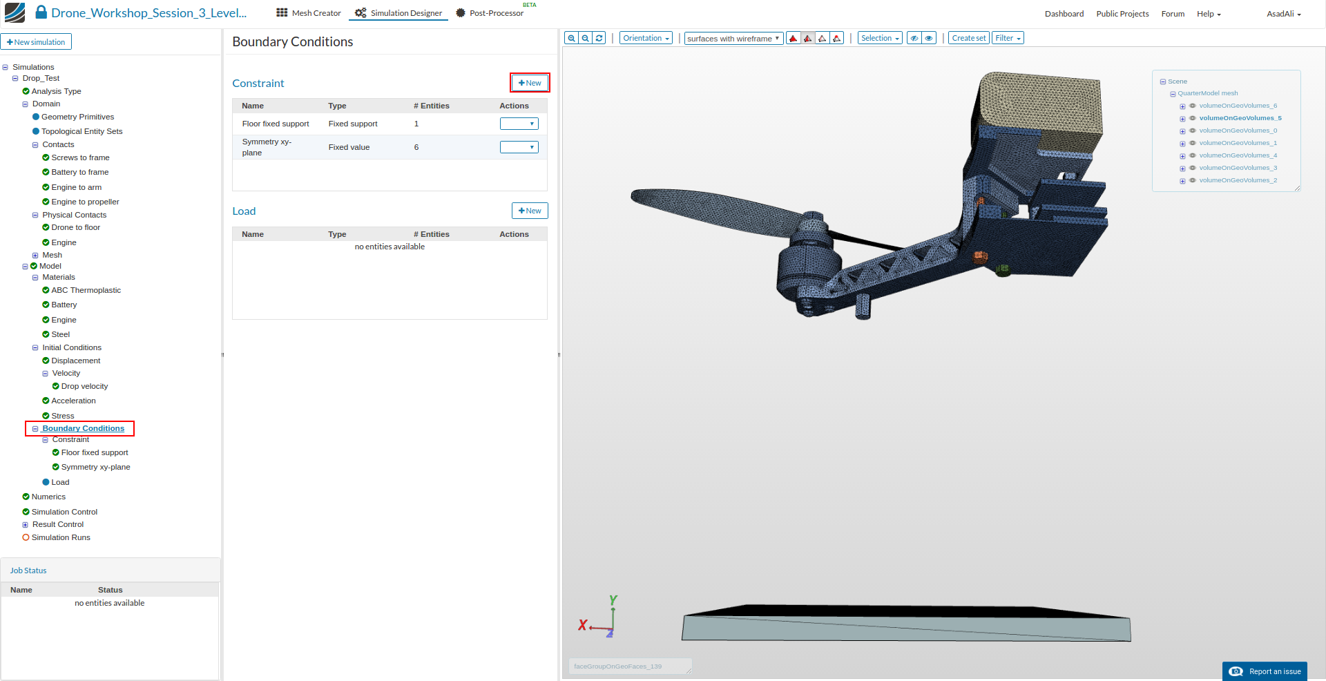
Next we can start to define the boundary conditions. Click on the Boundary Conditions item in the project tree.
There are two kinds of boundary conditions for structural simulations.
- Constraint conditions are used to limit the degrees of freedom of the model.
- Load conditions are applying an external load to the model
Due the fact that there is now external load or force on the model, we only need to define three constraint boundary conditions.
To create a new constraint boundary condition please click on the relevant button in the middle column window.
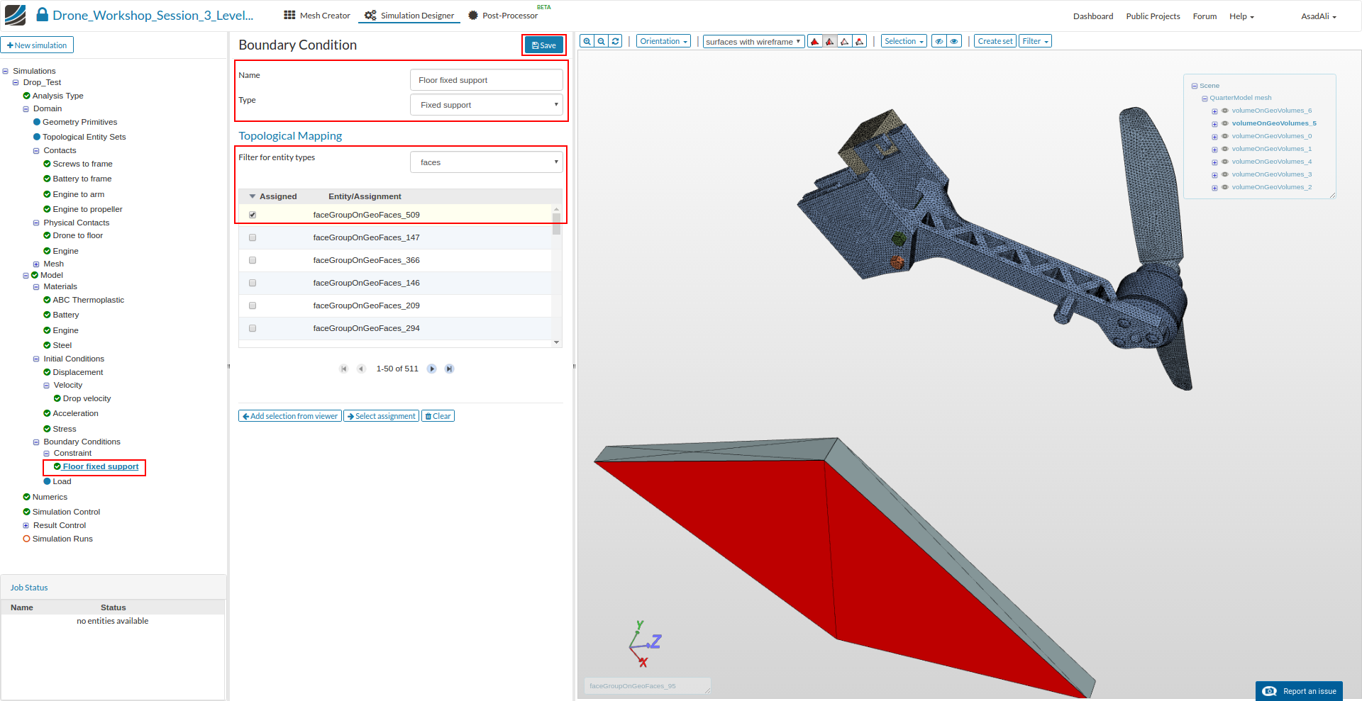
Floor fixed support
The role of this boundary conditions is to fix the floor.
- Name: Floor fixed support**
- Type: Fixed support
Finaly, assign this boundary condition to the lower face of the floor (FaceGrouponGeoFaces_609).
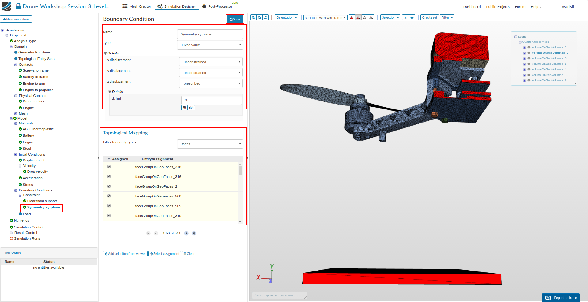
Symmetry xy-plane
This boundary condition is required because we are using a quarter model of the drone.
Create a new constrait boundary condition by clicking on the relevant button.
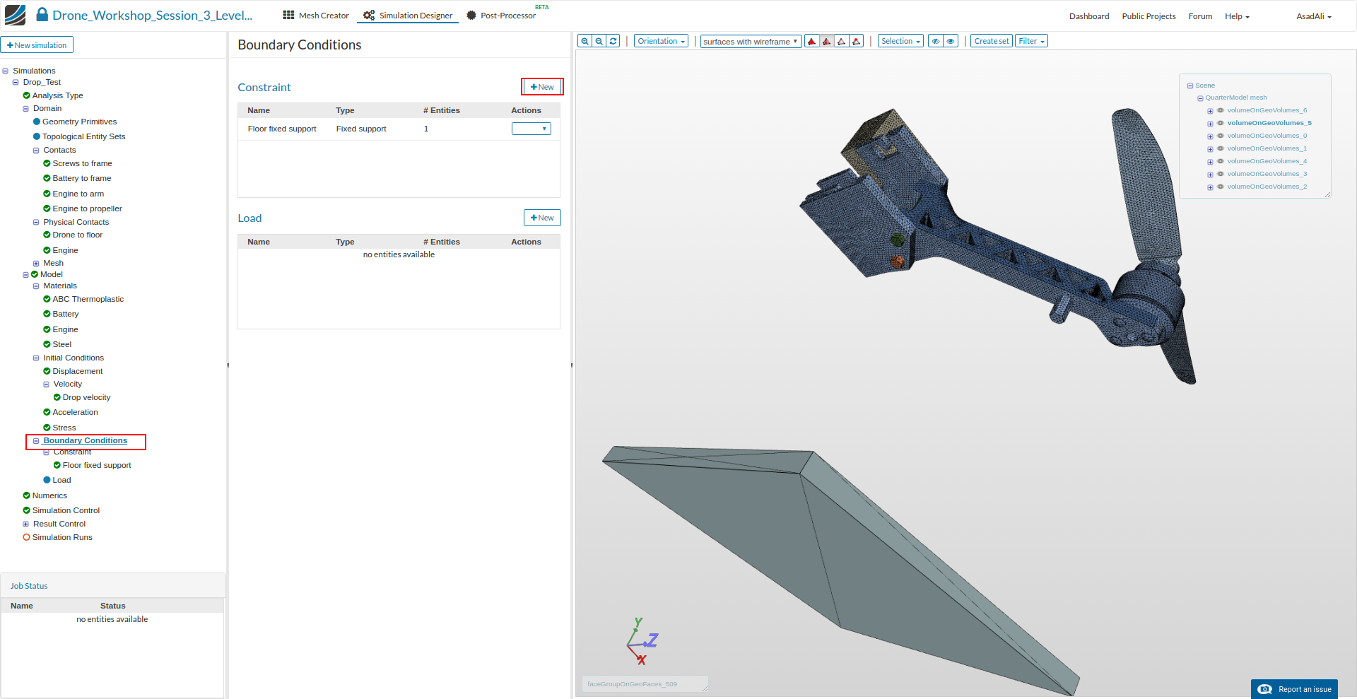
- Name: Symmetry xy-plane
- Type: Fixed Value
- x displacement: unconstrained
- y displacement: unconstrained
- z displacement: prescribed with a value of 0
Please assign all surfaces of the drone base plates which are bounding with the imaginery xy-symmetry plane and therefore behaving like a symmetry plane (faceGroupOnGeoFaces_2, faceGroupOnGeoFaces_310, faceGroupOnGeoFaces_316, faceGroupOnGeoFaces_378, faceGroupOnGeoFaces_500, faceGroupOnGeoFaces_505)
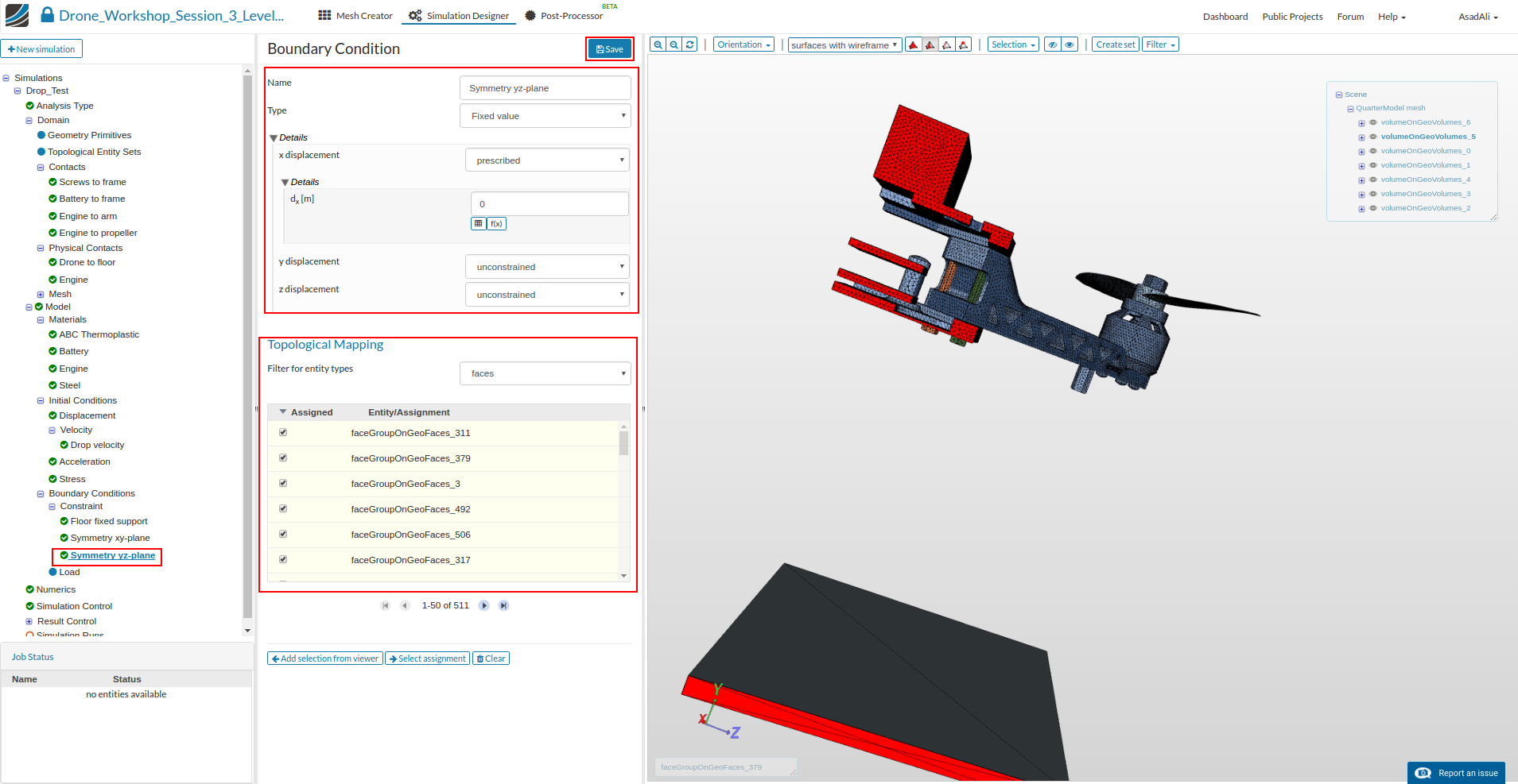
Symmetry yz-plane
This boundary condition is required because we are using a quarter model of the drone.
Create a new constraint boundary condition by clicking on the relevant button.
- Name: Symmetry yz-plane
- Type: Fixed Value
- x displacement: prescribed with a value of 0
- y displacement: unconstrained
- z displacement: unconstrained
Assign all surfaces of the drone base plates which are bounding with the imaginery yz-symmetry plane and therefore behaving like a symmetry plane (faceGroupOnGeoFaces_3, faceGroupOnGeoFaces_311, faceGroupOnGeoFaces_317, faceGroupOnGeoFaces_379, faceGroupOnGeoFaces_479, faceGroupOnGeoFaces_492, faceGroupOnGeoFaces_506).
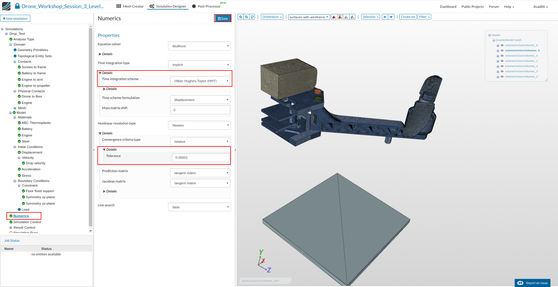
Next we will modify the numerical settings of our simulation to increase stability and speed. Click on the Numerics item in the project tree. This will open a new middle column menu where you can adapt the numerical schemes and tolerances:
-
Time integration type: implicit
-
Time integration scheme: Hilb-Hughes-Taylor (HHT)
-
Nonline resolution type: Newton
-
Convergence criteria: relative
-
Tolerance: 0.00001
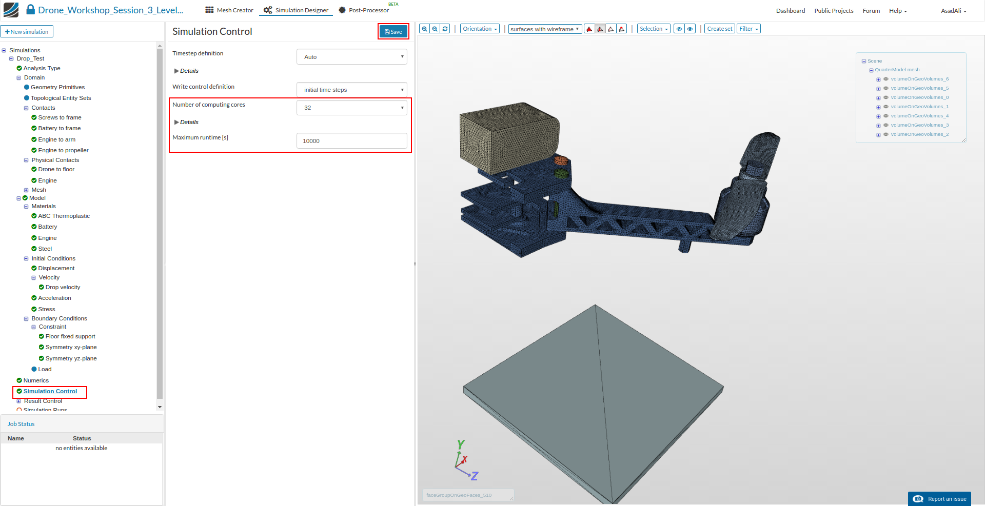
Click on the Simulation Control item in the project tree to specify how fast and accurate you want the simulation to be computed. Since we are running a dynamic simulation, we also have to care about the time step length.
The time step length can be comprehended similarly to the mesh size. It should be as a large as possible and as small an necessary. Due the fact that there will be only negligibly small stresses before the impact, we will use a large time step during the ‘free fall’ and a smaller time step before and during the impact.
- Timestep definition: Auto
- Simulation interval: 0.016
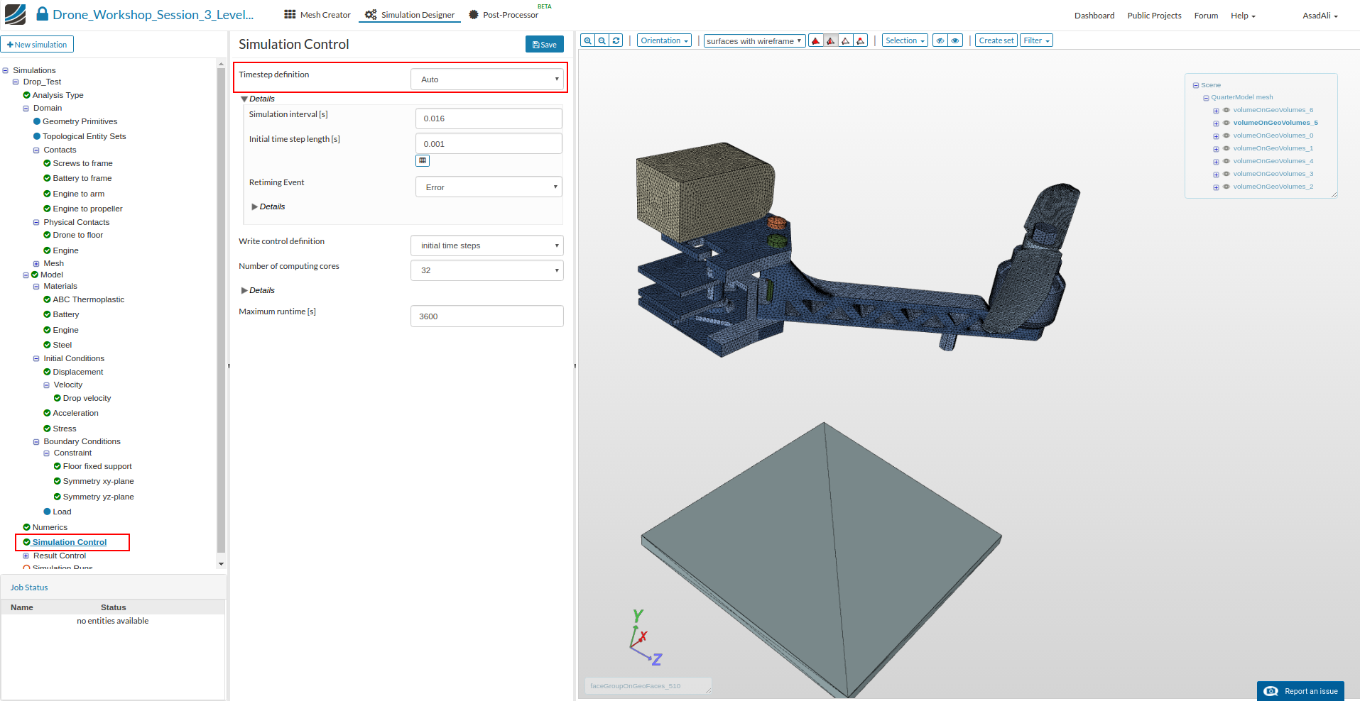
Note that you need for every fall velocity a different Simulation interval
- 1m/s = 0.1
- 2m/s = 0.0548
- 5m/s = 0.027
Now click on the table icon under the field for Initial time step length.
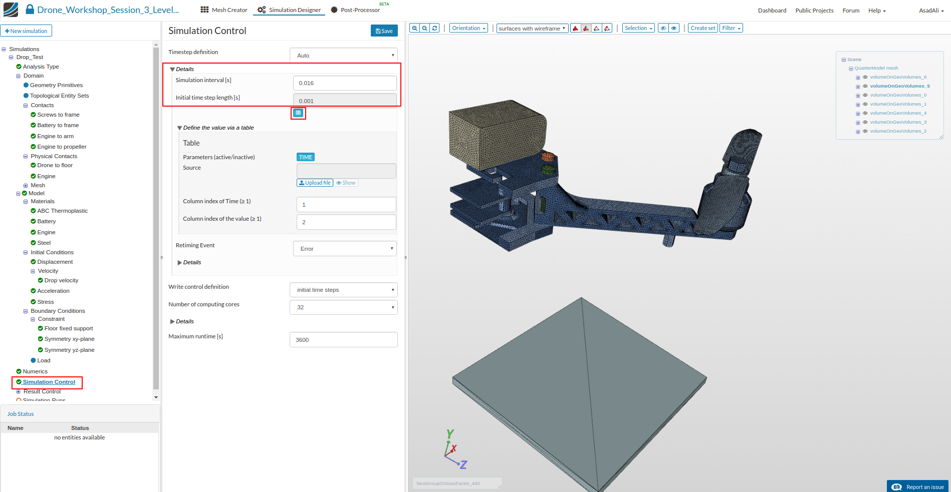
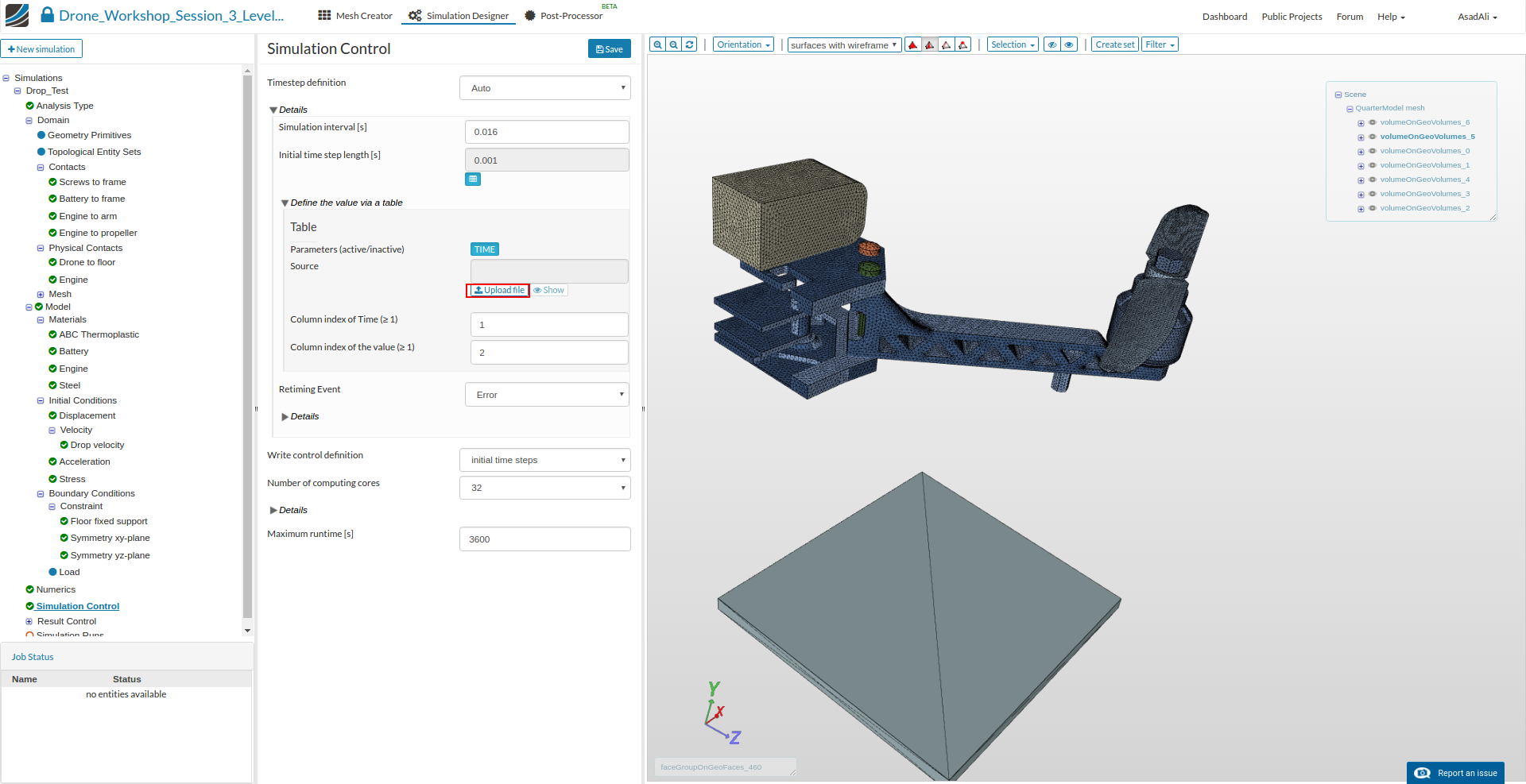
This will expand the middle column menu. We will now upload a CSV file which describes the time step lenghts for the different stages of the simulation.
Note that you need for every falling velocity a different CSV file. We are providing all CSV files for the homework below.
CSV file for 1m/s
CSV file for 2m/s
CSV file for 5m/s
CSV file for 10m/s
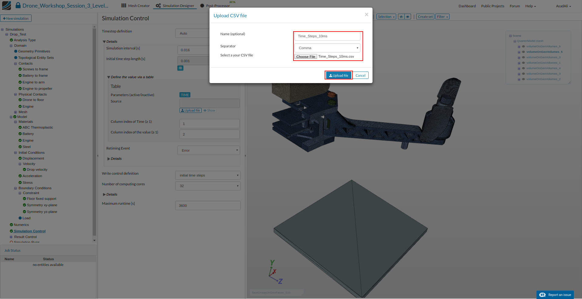
Click on the Upload file button and select the CSV file ‘Time_Steps_10ms.csv’. Make sure that you use Comma as the separator.
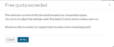
Finally change the number of computing cores to 32 and change the Maximum runtime to 10000
Click on the Result Control item in the project tree which will open a new middle column menu.
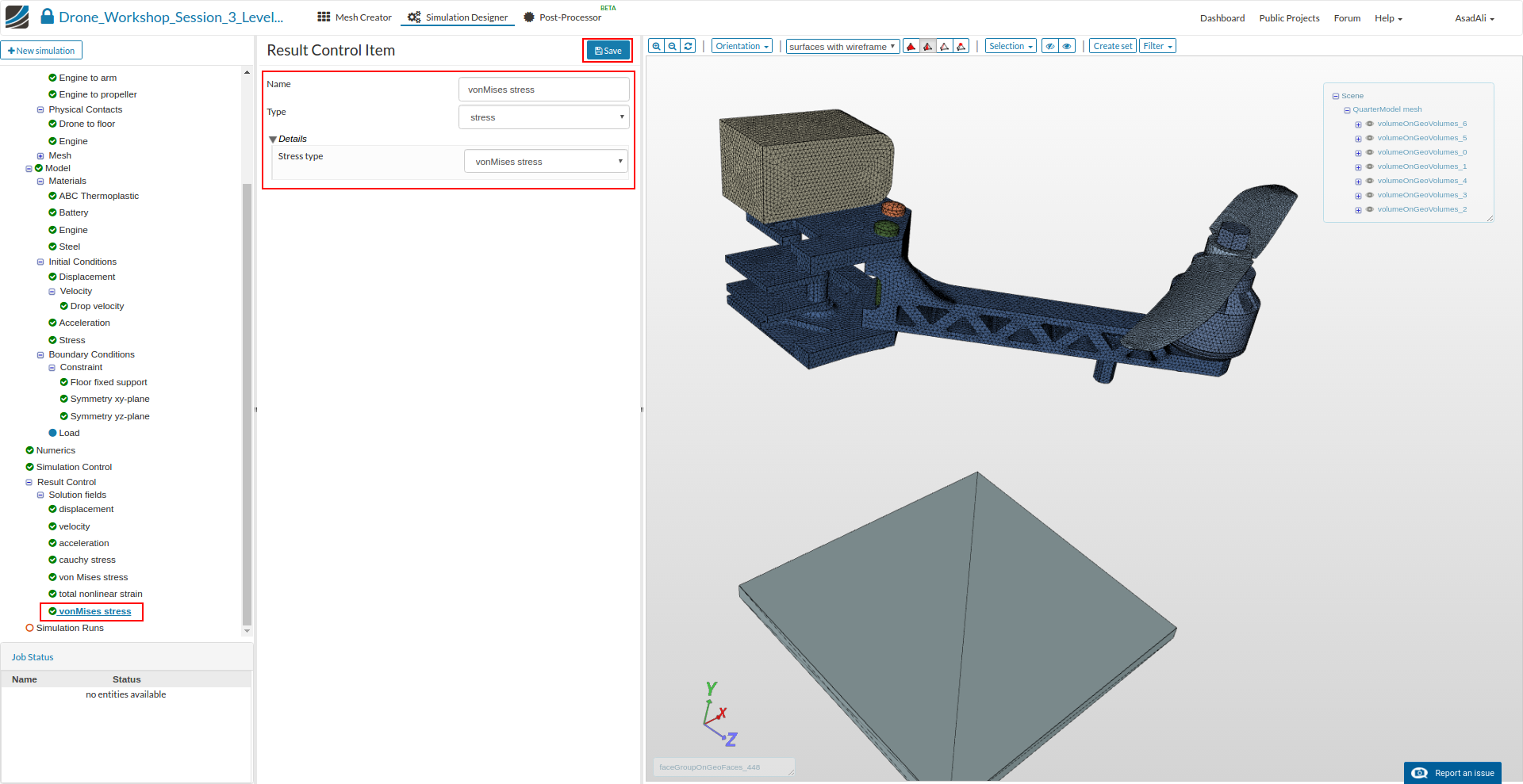
Now we will add some additional Solution Fields defining which physical quantities should be calculated during the simulations. Click on the New sub-item in to add Solution field item.

Choose the result field you want to add from the drop-down menu in the middle column:
- Name: vonMises stress
- Type: stress
- Stress type: vonMises stress
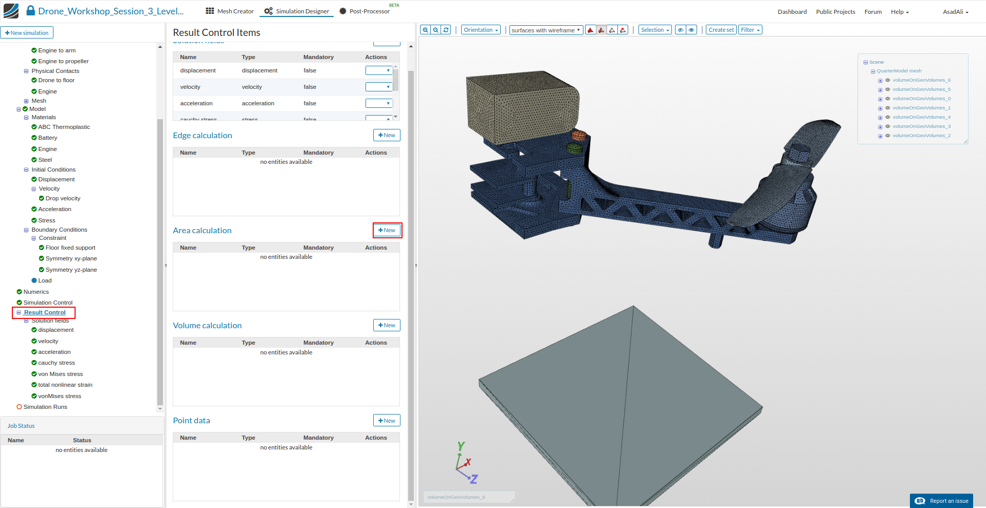
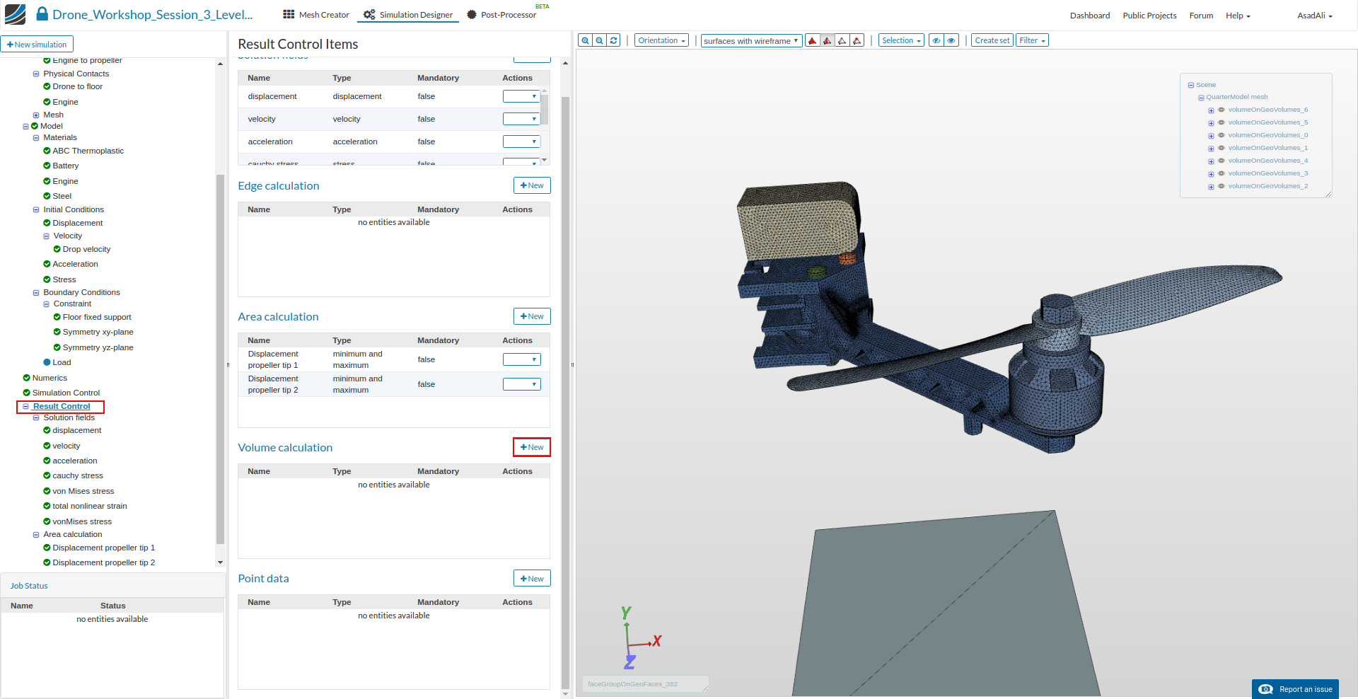
Next we will also add other Result Control items to simplfy the result interpretation.
To add them, click again on the Result Control item in the project tree.
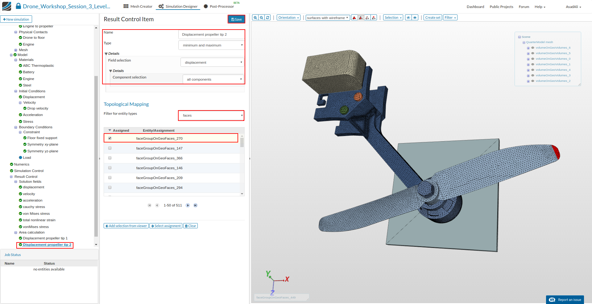
Then click on New against the ** Area calculation** item.
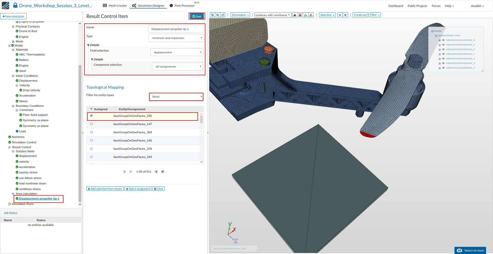
Now define the Result Control item as follows:
- Name: Displacement propeller tip 1
- Type: minimum and maximum
- Field selection: displacement
- Component selection: all components
Map it to the upper surface of the tip of the propeller (faceGroupOnGeoFaces_255).
Please repeat this workflow to create an additional result control item for the opposite tip of the propeller:
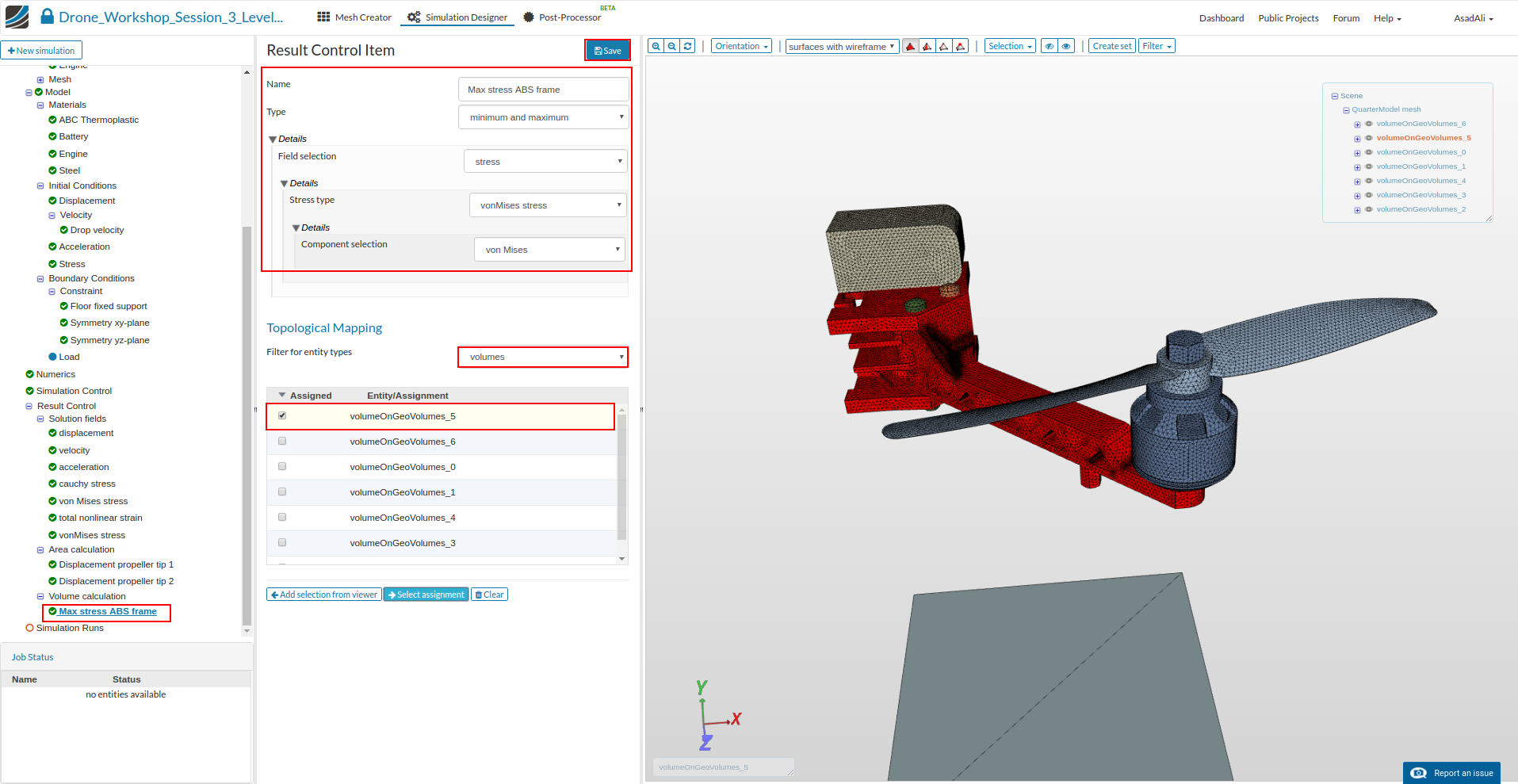
Finally we will add a Volume calculation result control item to get the highest stress in the drone chassis.
Create a new result control item by clicking the New against the Volume calculation item.
Now define the Result Control item as follows:
- Name: Max stress ABS frame
- Type: minimum and maximum
- Field selection: stress
- Stress type: vonMises stress
- Component selection: von Mises
Map it to the volume of the frame (volumeOnGeoVolumes_5).
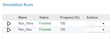
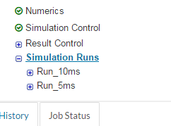
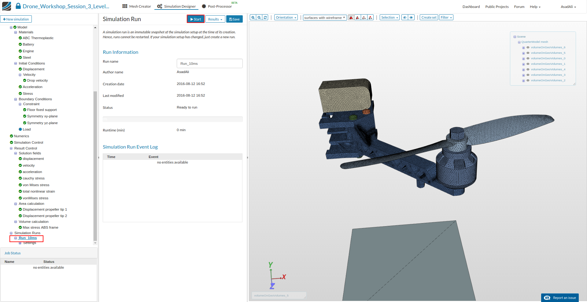
To start the simulation, click on the Simulation Run item in the tree and click on the Create new run button at the bottom of the middle column menu. This will create a snapshot of your simulation settings as a new sub-item.

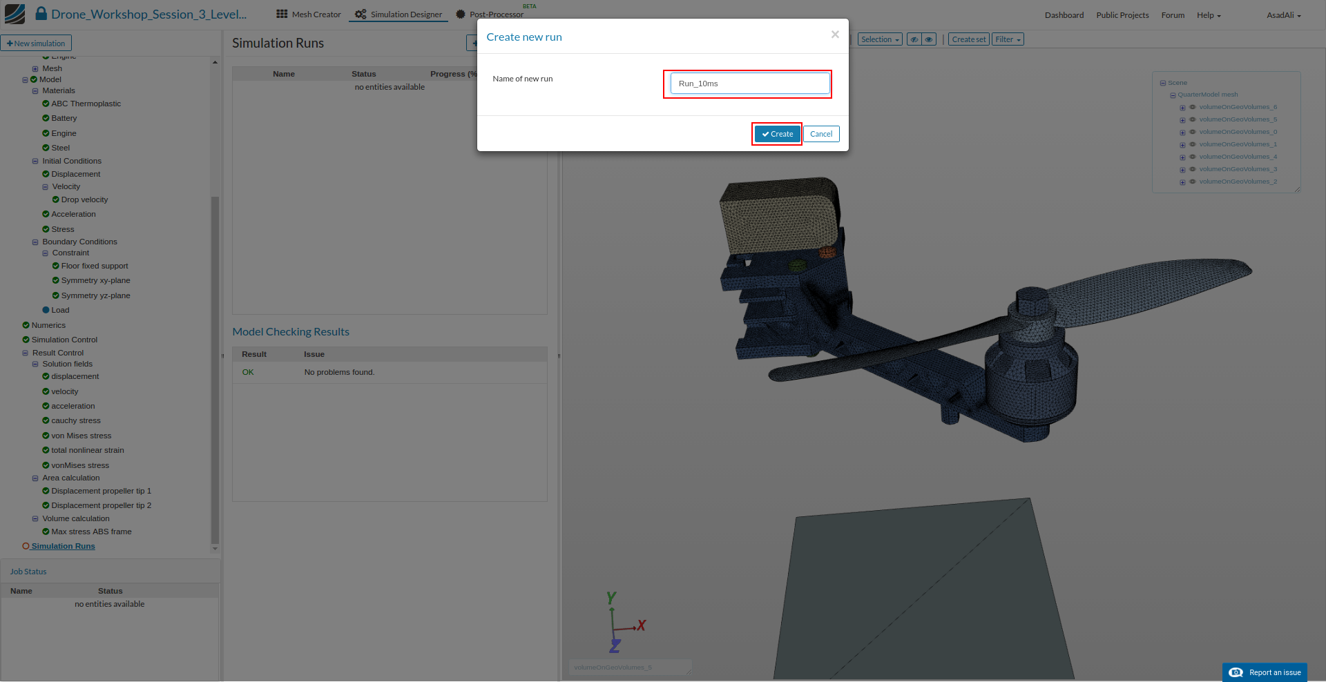
You can now start the simulation run by selecting it from the project tree and then click on the Start button.
Important note
It is not necessary to set up the simulation from scratch in order to simulate the other 3 falling velocities. You can just modify your simulation and create a new run. Since this is a dynamic simulation, you should make sure to update the following settings.
- To adapt the falling velocity you have to modify the initial conditions for velocity.
- Since a different falling velocity will impact the duration of the drop test, you also have to update some settings in simulation control.
- You have to change the Simulation interval to the according value as stated in the section above.
- You also have to use a different CSV file for time step length which you can download in the same section above.
Once your simulation is finished, please click on the Post-Processor button in the main ribbon bar.
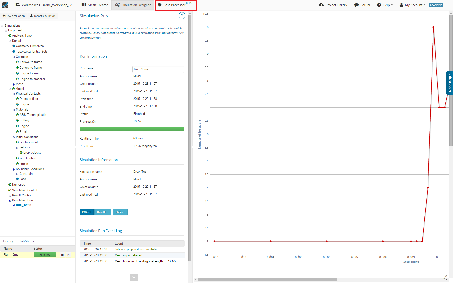
Post-processing
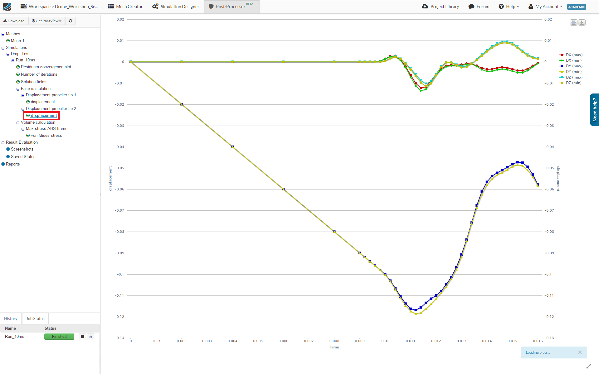
First of all, we will take a look at the Result Control item we added. Expand the Face calculation and the Volume calculation item in the project tree.
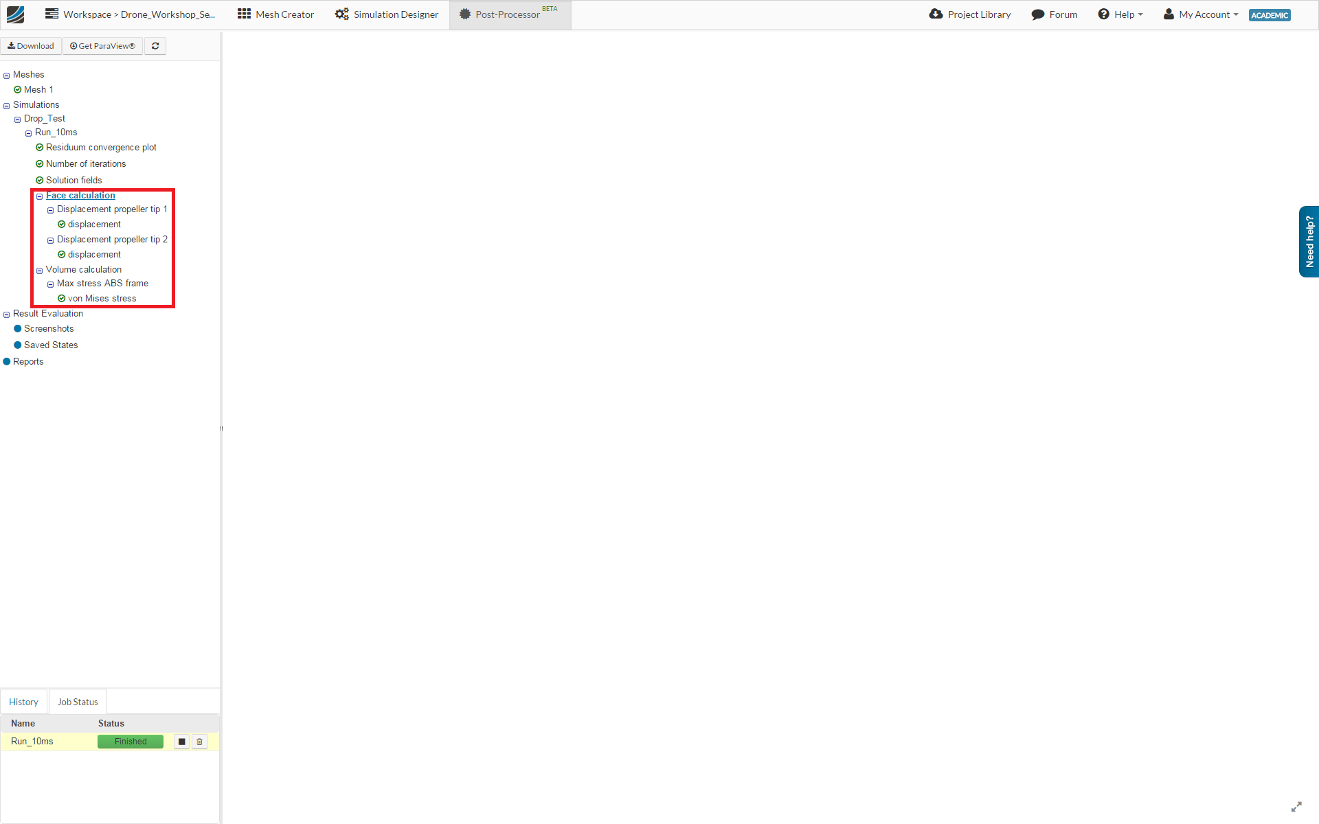
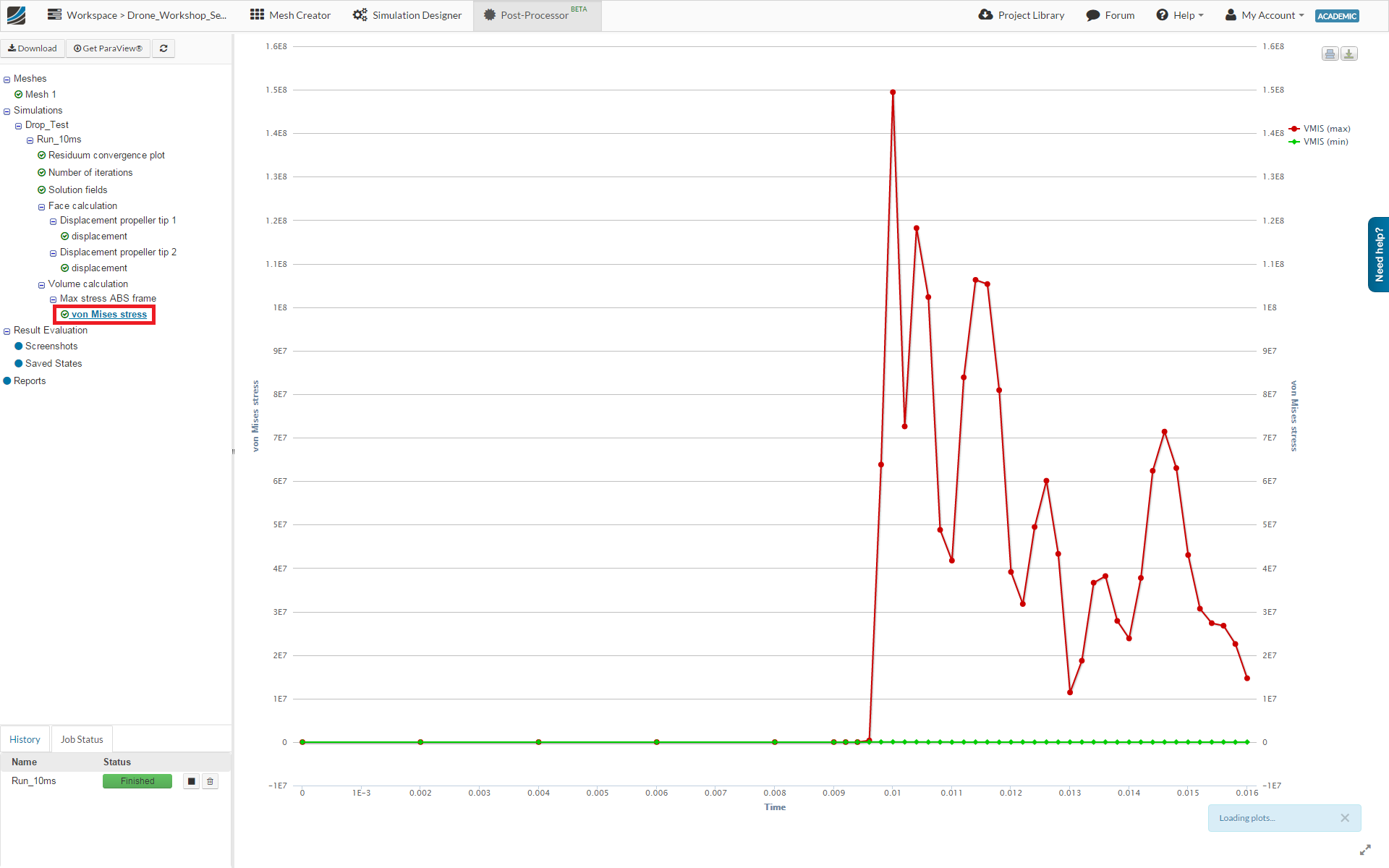
Clicking on the lowest elements of this tree will show you the plot of the relevant result control item.
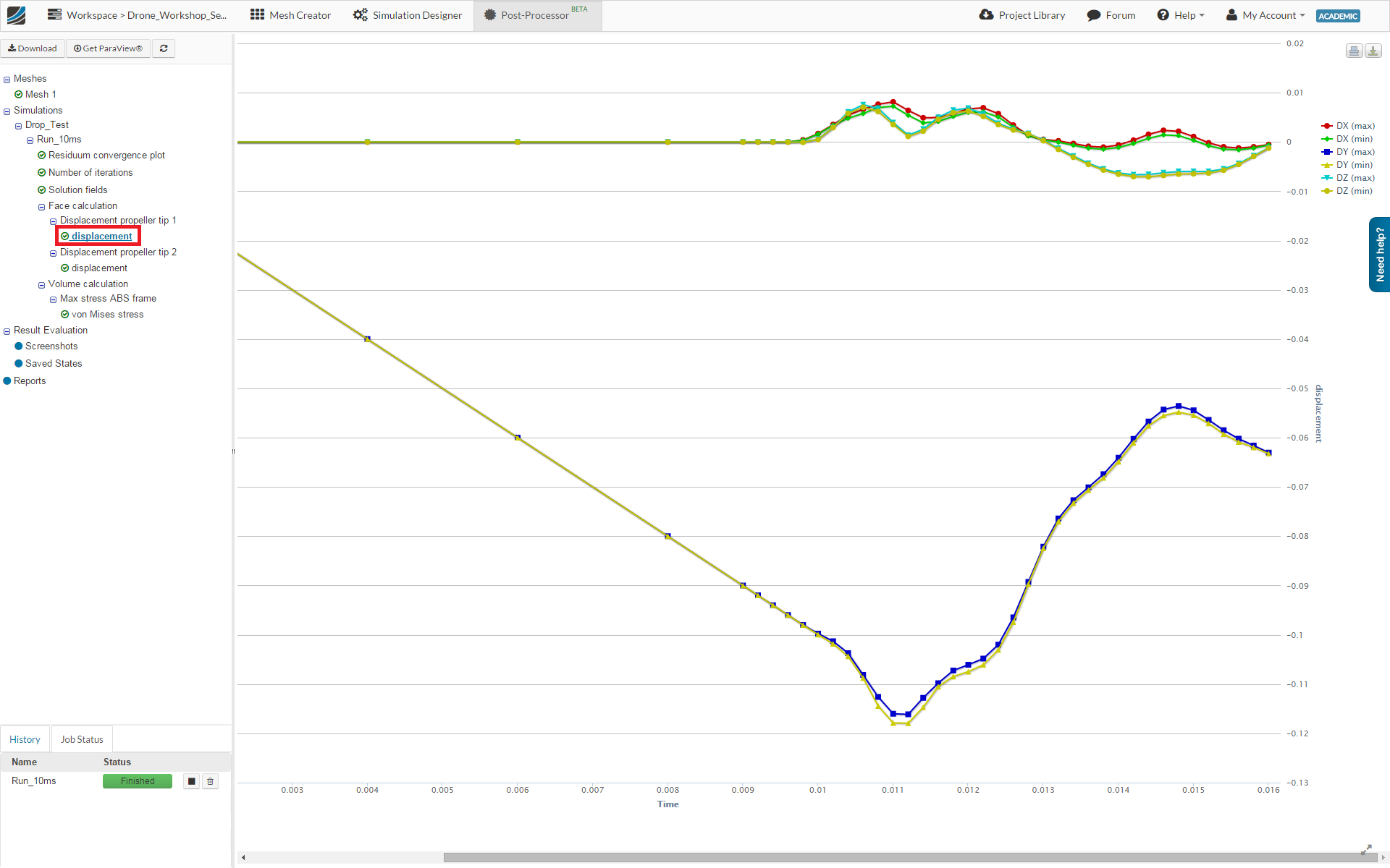
The graph shows the maximum von Mises stress in the drone frame versus the time.
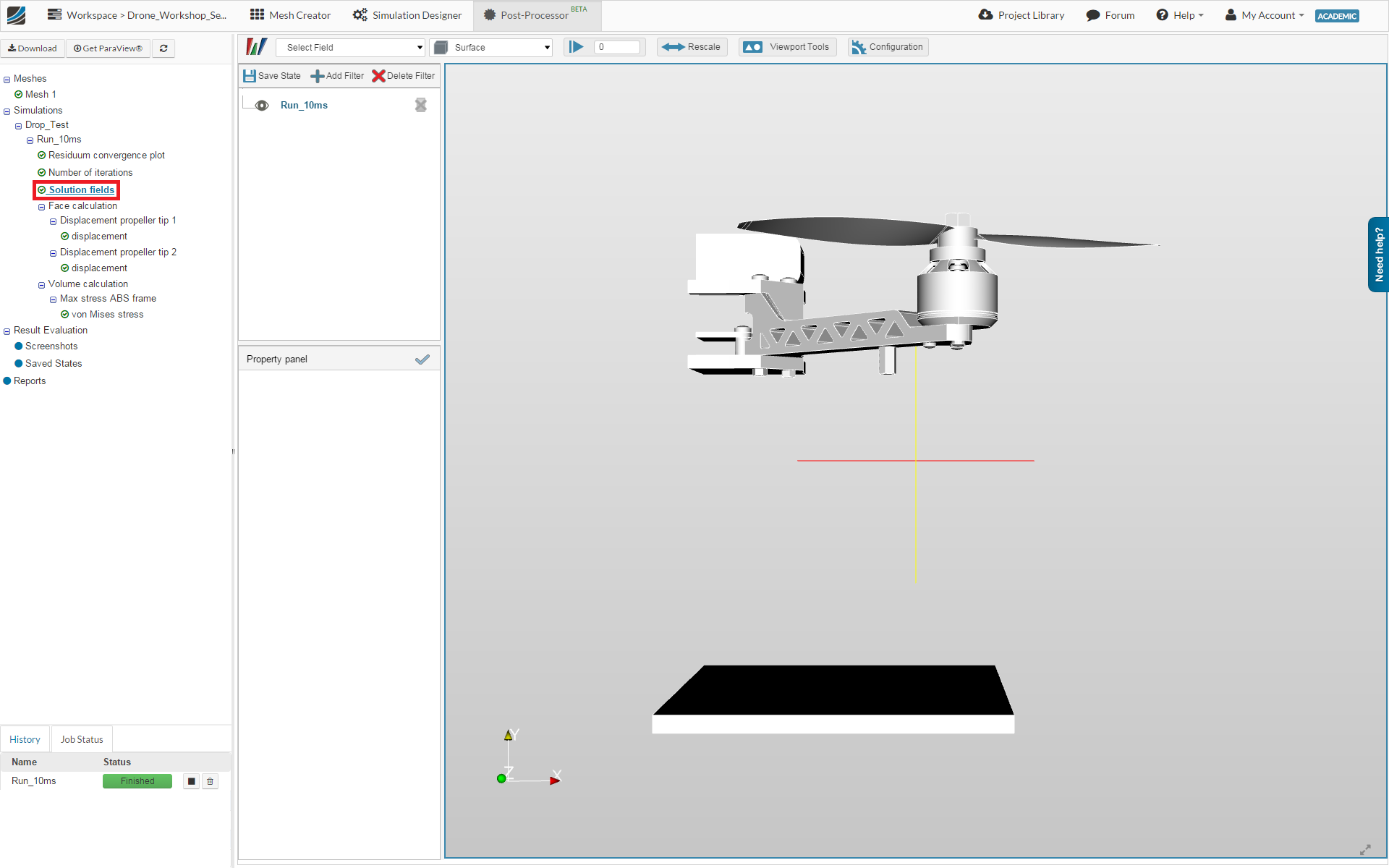
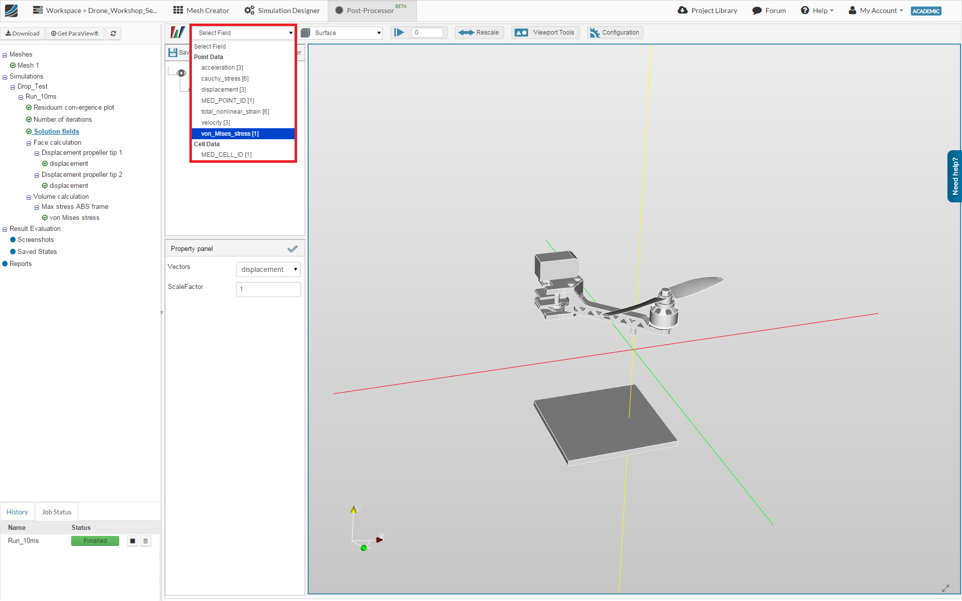
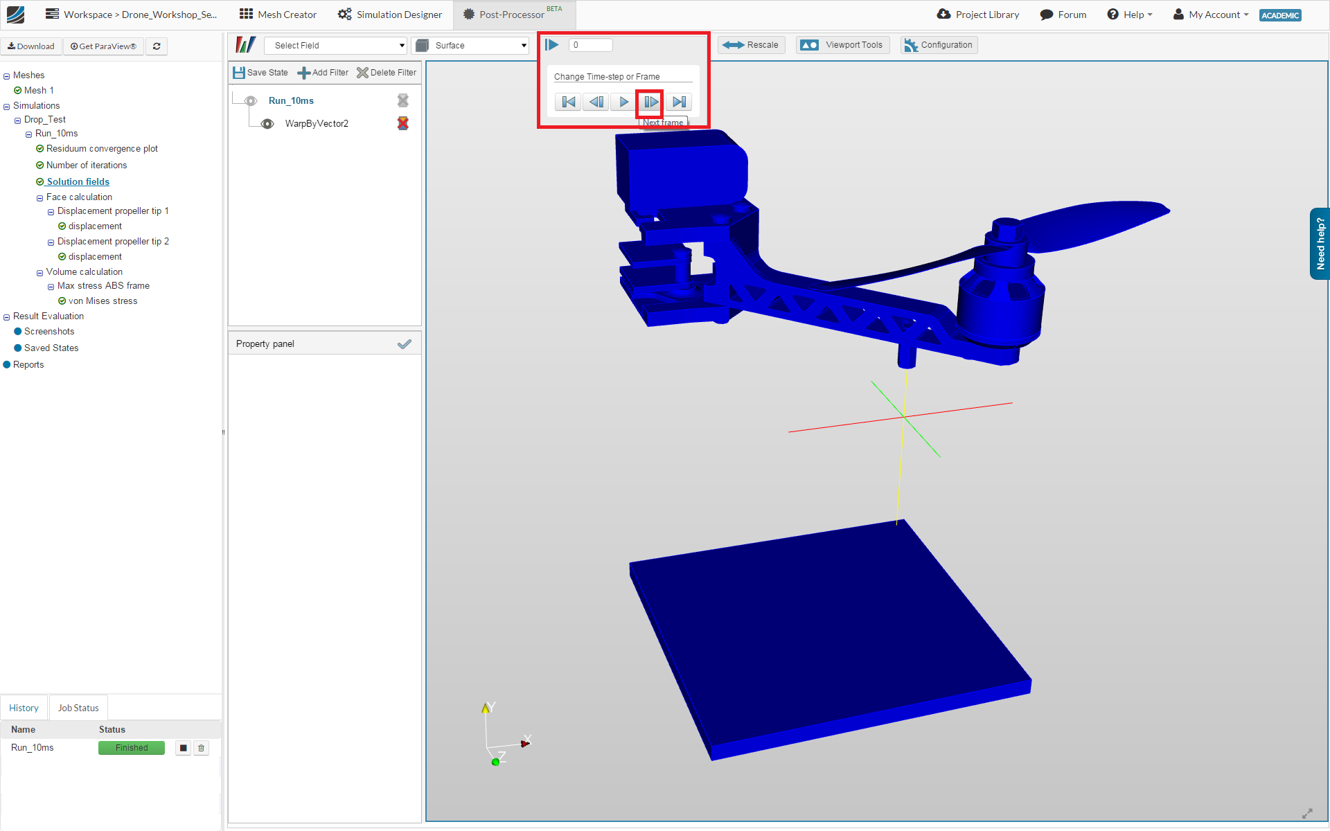
Next we will take a look at the 3D result. Click on the Solution fields in the project tree.
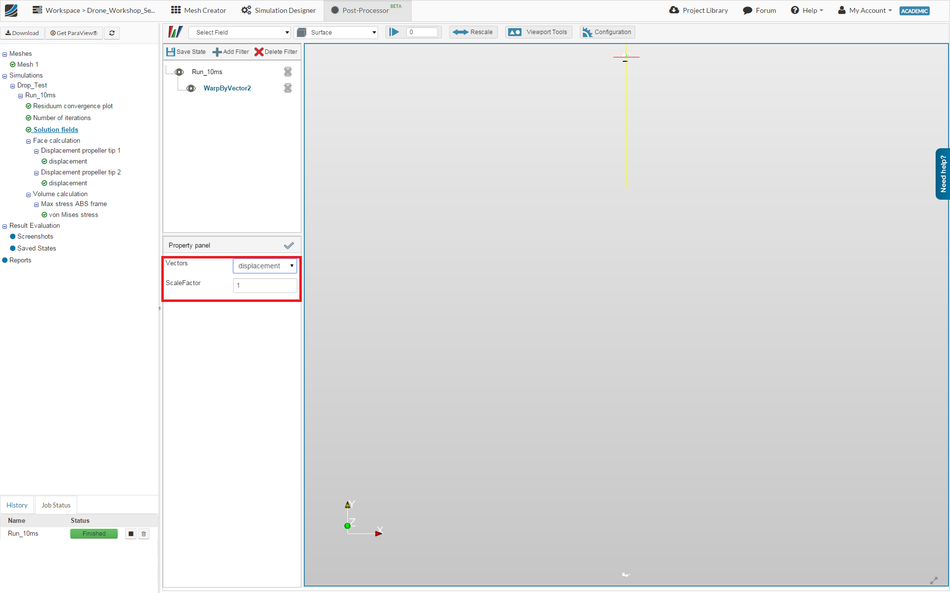
Click therefore on the Add Filter button and choose the WrapByVector filter from the list.
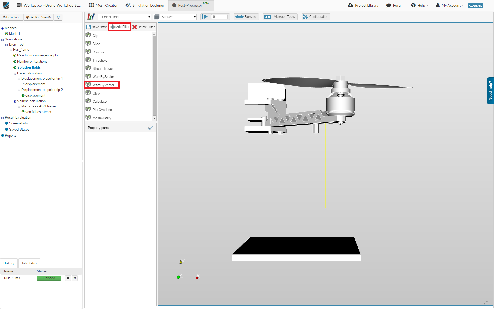
In the Property panel, you can define which Vector field you want to visualize and define a ScaleFactor.
- Vectors: displacement
- ScaleFactor: 1
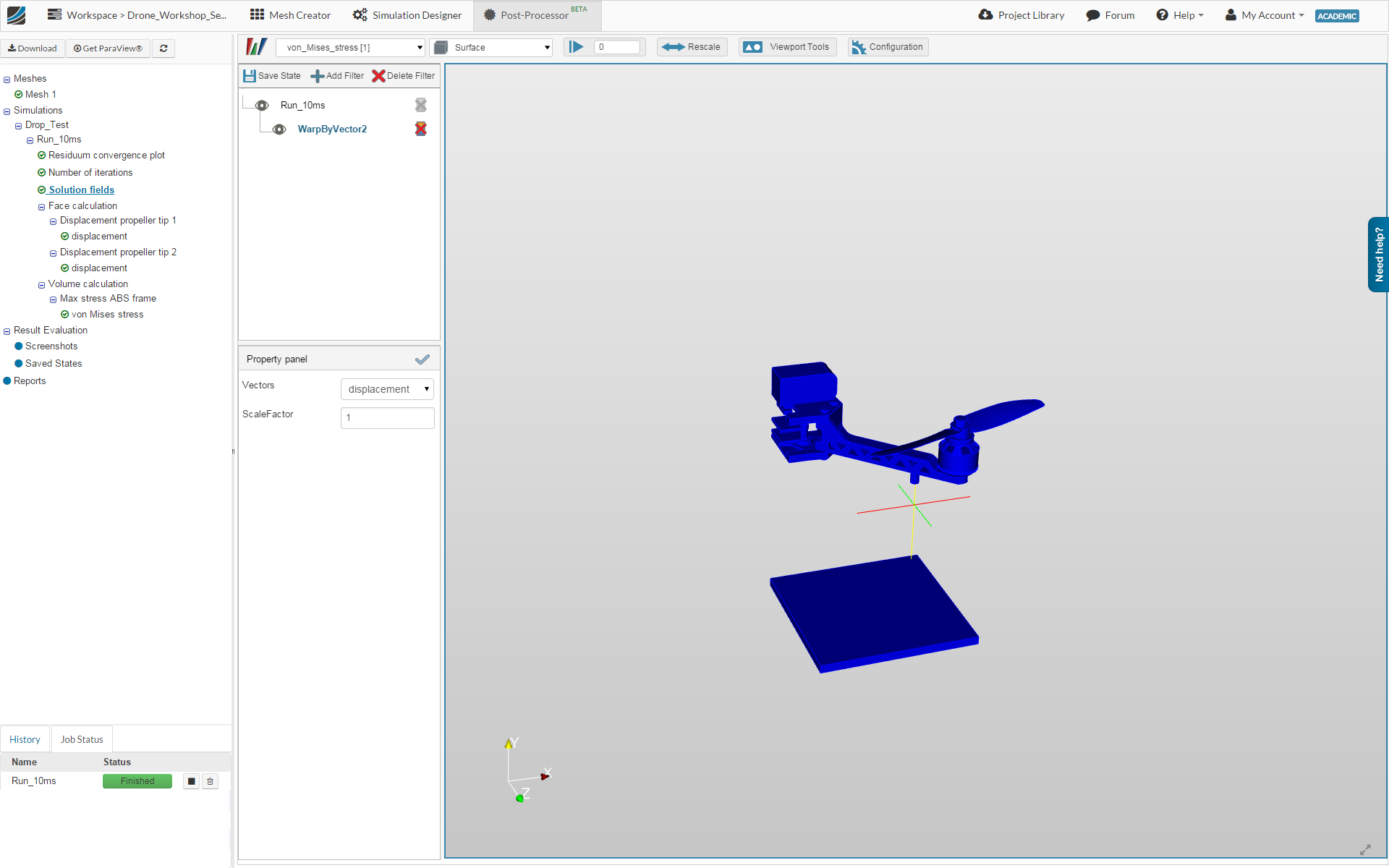
Now you are able to see how the arm will move and deform (grey body).
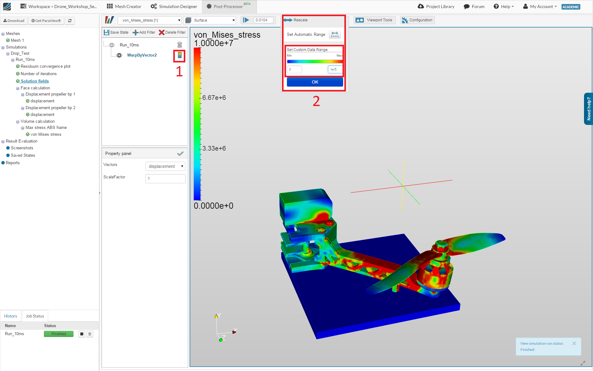
Next change the field representation to vonMises_stress
Using the Eyes symbol in the post-processing tree, you are able to hide and show the filters. Please hide the main entry Run_10ms.
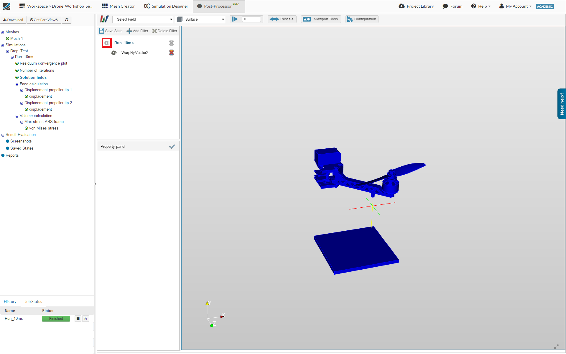
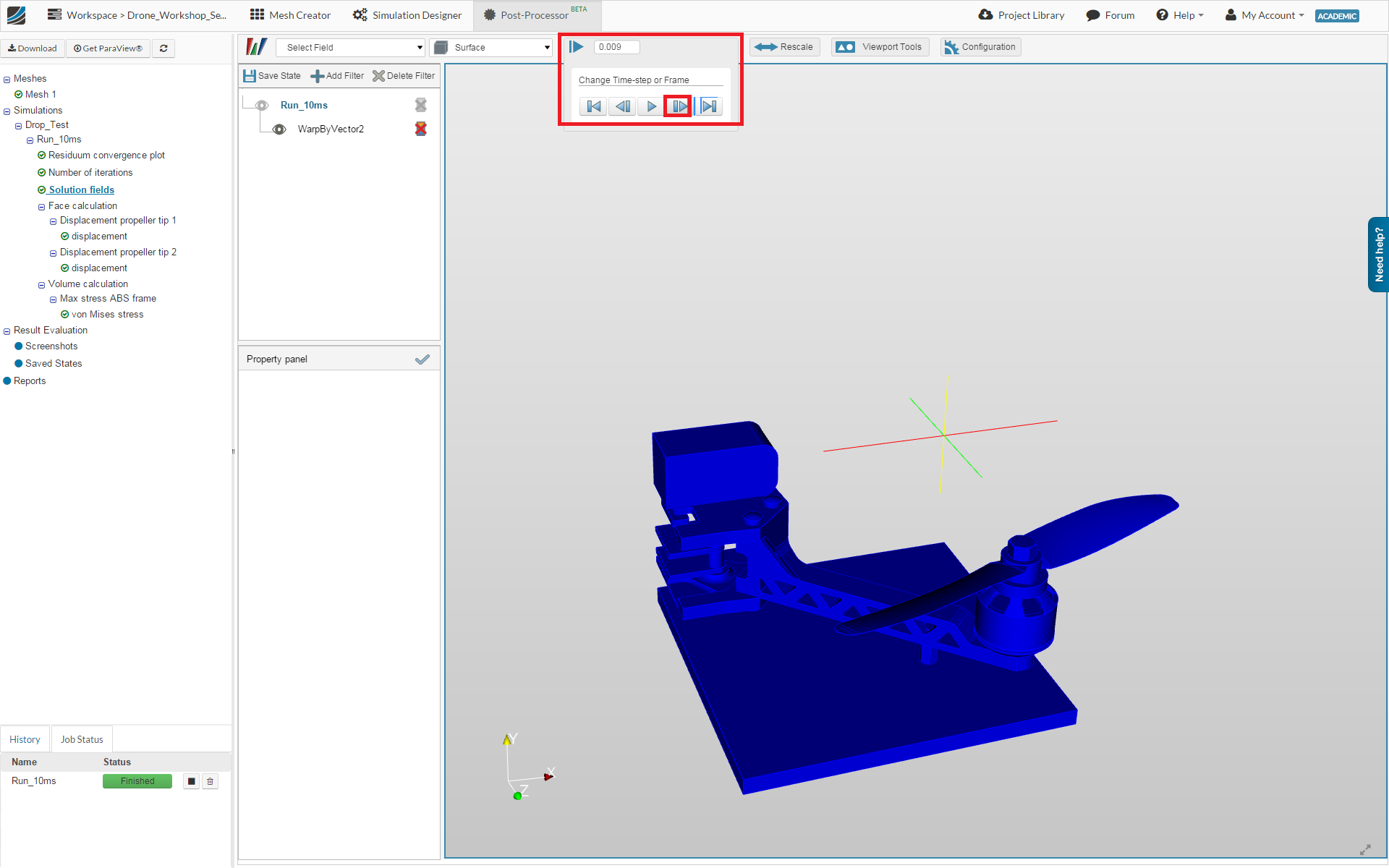
Now you can dive through the results by changing the time step. For this you have to use time step control bar.
Please note that it will be necessary to manually rescale the colour legend. For this, first activate the colour legend by clicking on the relevant item (1). Then open the Rescale widget where you can manually define a costum data range (2).
Congratulations, you have completed the Homework of Session 3 - Level 2 and can now move on to Session 4: