Recording

Homework submission
Submitting all three homework assignments will qualify you for a free Professional Training (value of 500€) as well as a certificate of participation.
Homework 1 - Deadline 16.06 4:00pm
Please use the form to submit your homework
Exercise

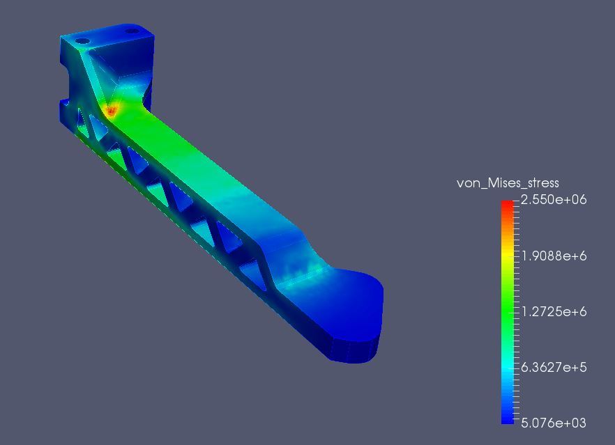
Our aim is to investigate the displacement of the drone arm for different lift forces. Therefore we will create a mesh of the arm and simulate the structural behavior of it for different forces (0.75N, 1.5N, 2.25N, 3N).
Your final homework project should contain 1 mesh and four simulation runs. You can submit your homework using the form.
NOTE: This tutorial was updated on 10/2016 to match the updated version of the platform
Step-by-Step Instructions
Meshing
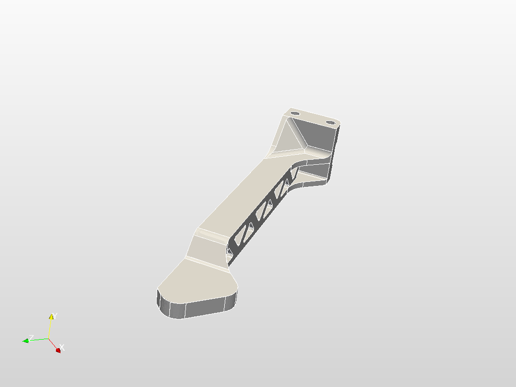
First of all you have to import the geometry into your SimScale workspace. For this, you only have to click on this link and a project with everything you need will be added to your workspace. Please note that this can take several minutes.
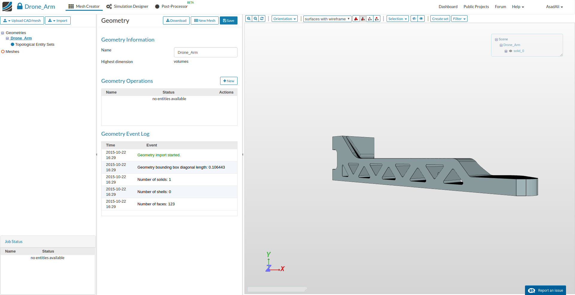
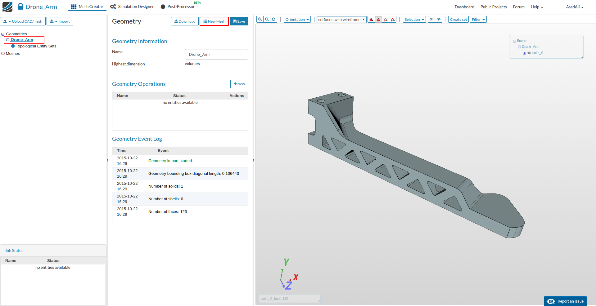
Once project is imported, select the geometry and press New Mesh to crate a new mesh setup for this geometry.
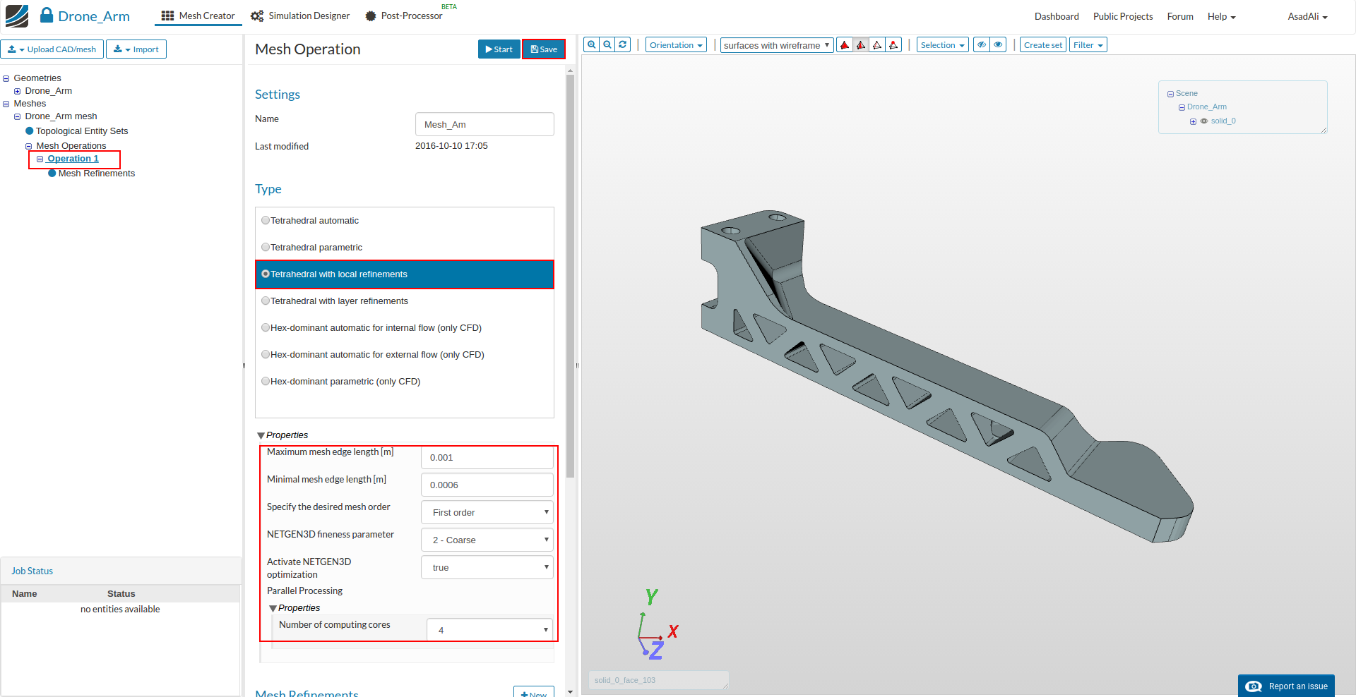
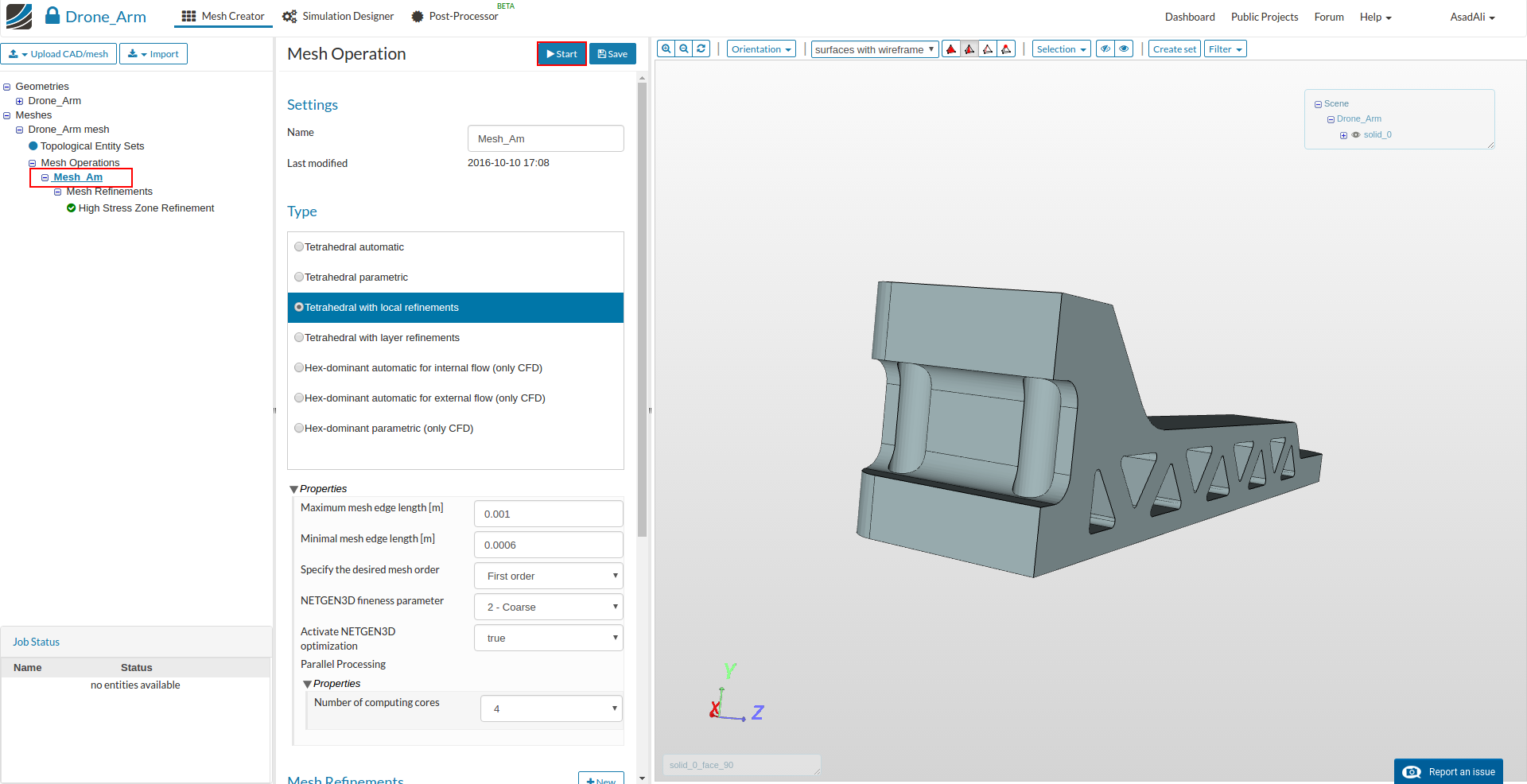
Here in the middle column select Tetrahedral with local refinements from the list and define following parameters:
- Maximum mesh edge length: 0.001
- Minimal mesh edge length: 0.0006
- NETGEN3D fineness parameter: 2 - Coarse
- Number of processors 4
Save the selection by clicking Save.
Now we have defined a range for the base mesh size which is fine for regions where we are not expecting high stress. Here you should keep in mind that, in general, the mesh size is related to the local accuracy of the simulation. It is therefore necessary to refine the mesh in those areas where high stresses are expected.
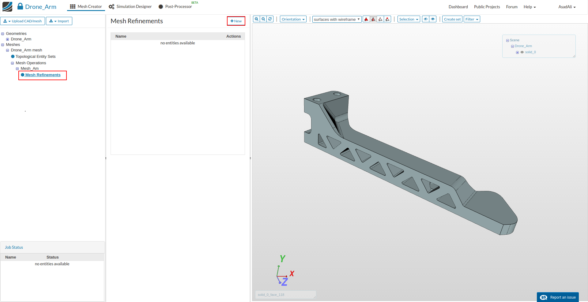
We will now apply local refinements on the faces where we expect high stresses and high deformations.
Click on the Mesh Refinements item which was added to the project tree. This will open again a menu in the middle column where all refinements are listed and where you can add new refinements by clicking New.
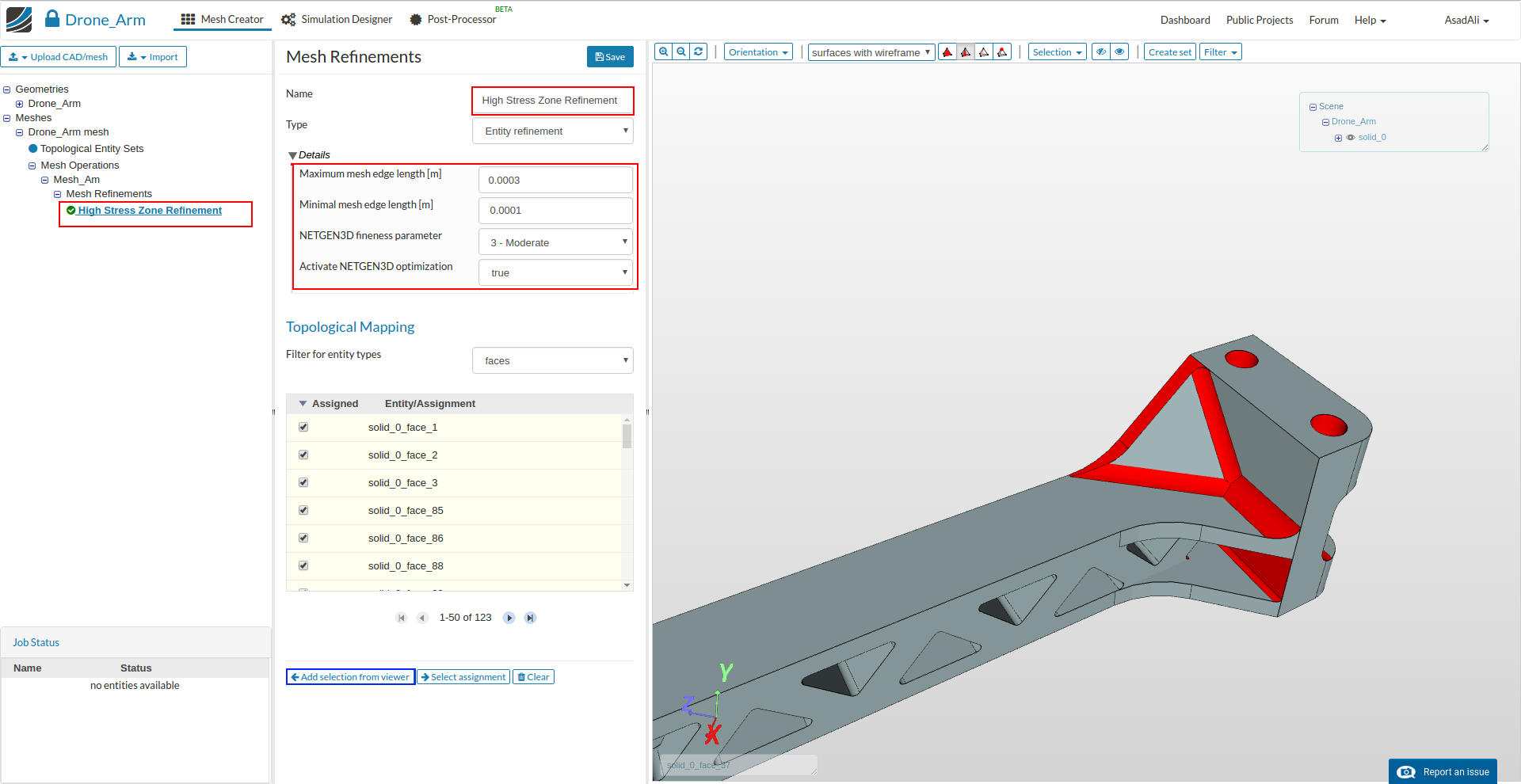
Set the parameters as:
- Name: High Stress Zone Refinement
- Maximum mesh edge length: 0.0003
- Minimal mesh edge length: 0.0001
- NETGEN3D fineness parameter: 3 - Moderate
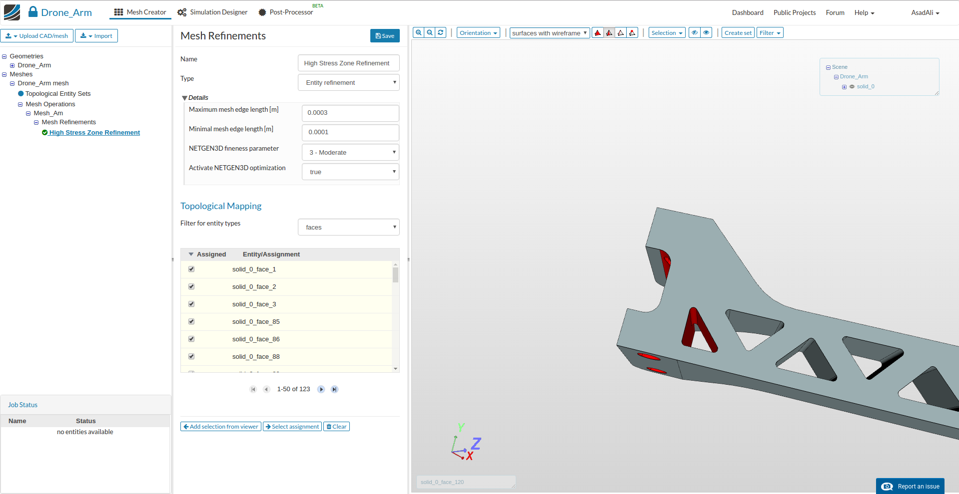
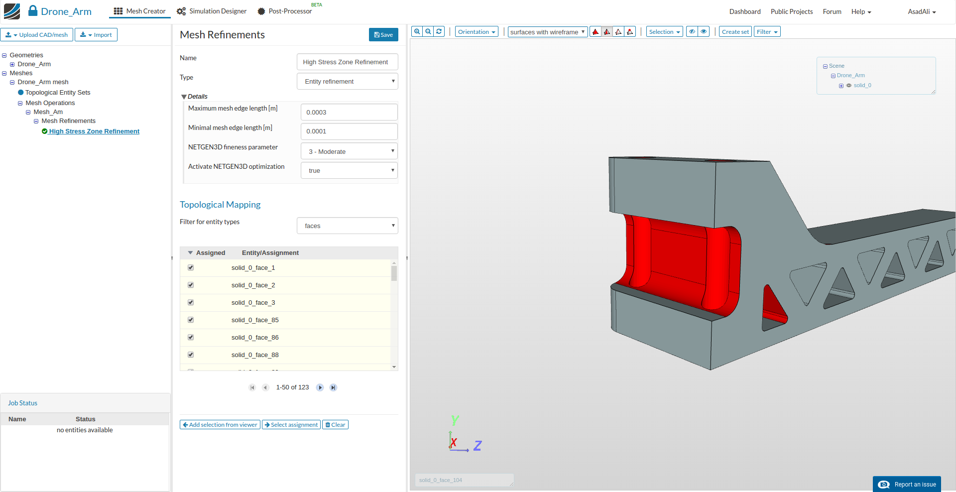
Next, select the faces you want to apply this refinement.
It is also possible and recommended to select the faces which you want to assign to the refinement graphically. Therefore you have to select the faces in the 3D model window on the left side by clicking on them with the left mouse button; to add them to the list, just click on the Add selection from Viewer button in the middle column.
Now our mesh is ready for computation. Click on the meshing operation in the project tree and click the Start button.
Simulation Setup
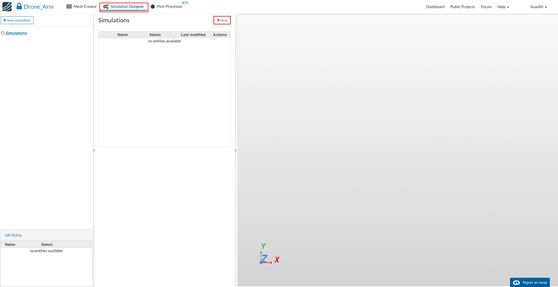
After the mesh is completed we will set up the simulation. Click on the Simulation Designer button in the main ribbon bar and click New to create a new simulation setup.
This will open an additional column in the middle. Here you can select which kind of simulation you want to run. In our case we will run a Static Analysis simulation with a Non-linear option set to “false”.
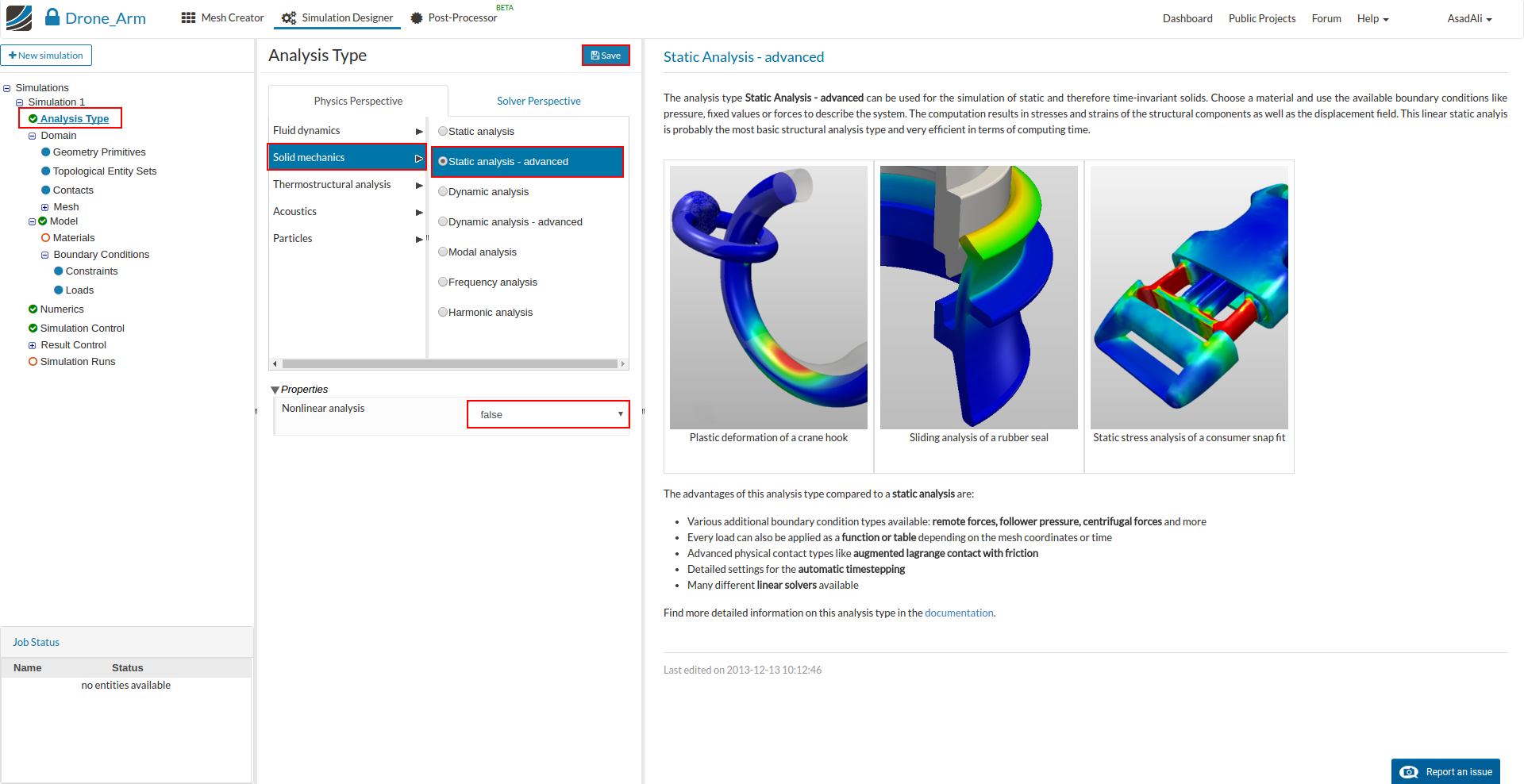
Going forward, this tree will guide us through all necessary steps. Please note that some of the items are optional or not necessary and will therefore be skipped
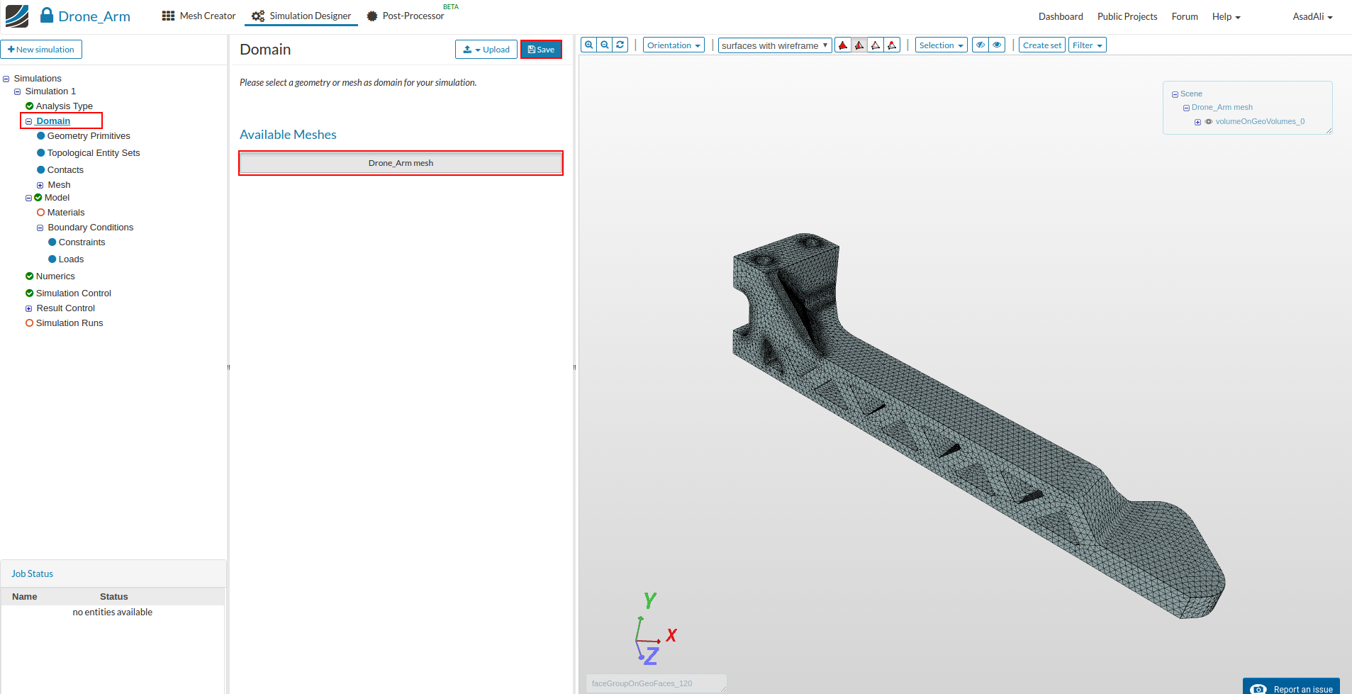
Next you have to specify which mesh you want to use for your simulation. Click on Domain item in the project tree and select “Drone_Arm mesh” from the menu which disappears in the middle column. Don’t forget to save your selection.
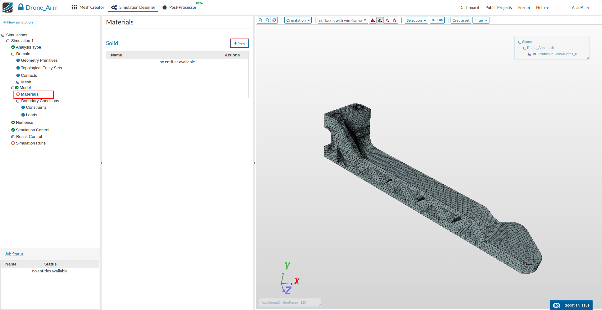
Now you can define your new material based on your own material proporties or access our Material Library which includes ready-to-use material models for several materials.
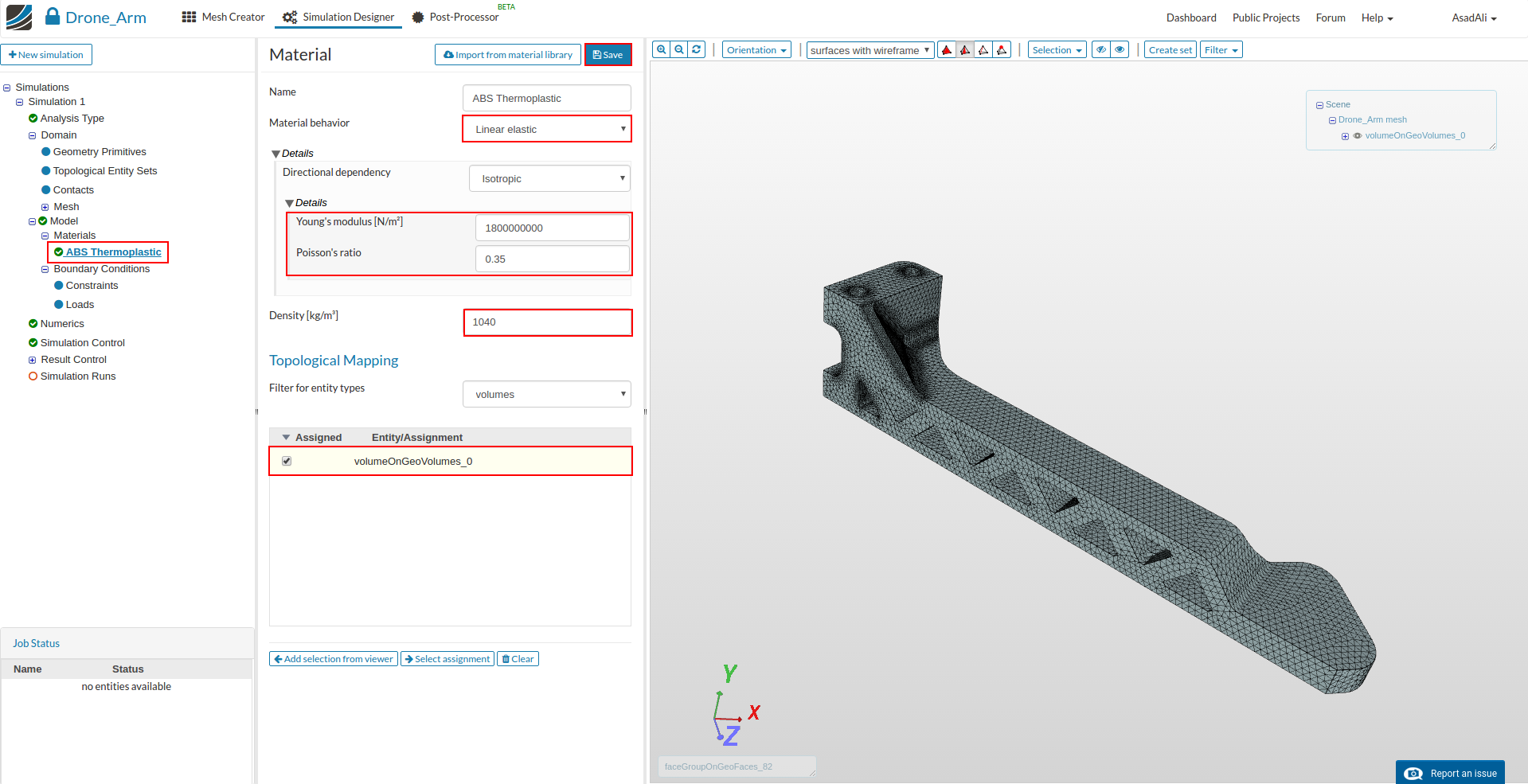
We will manually manual define an ABS Thermoplastic. Click therefore on the Materials item in the project tree. This will open a middle column menu where you can create a new material by clicking the related New button.
- Name: ABS Thermoplastic
- Young’s Modul: 1800000000
- Poisson’s ratio: 0.35
- Densiy: 1040
Now assign the material to volume of the arm (volumeOnGeoVolumes_0)
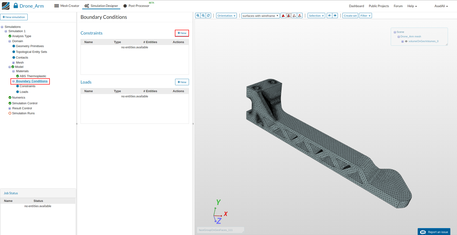
Next we can start to define the boundary conditions. Click on the Boundary Conditions item in the project tree.
There are two kinds of boundary conditions for static structural simulations.
- Constraint conditions are used to limit the degrees of freedom of the model.
- Load conditions are applying an external load to the model
First we will define a constraint boundary condition to fix the arm. Click therefore on the New button for the constraints.
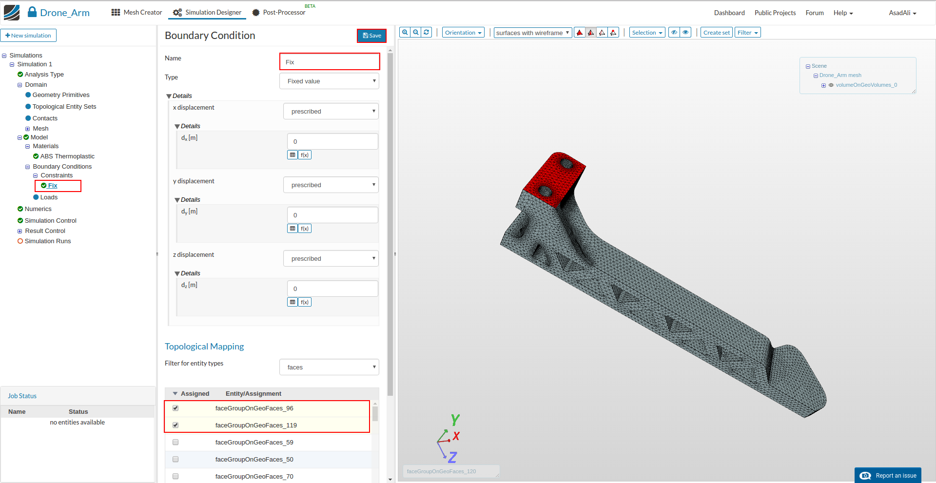
- Name: Fix
- Type: Fixed Value
- x displacement: prescribed wit a value of 0
- y displacement: prescribed wit a value of 0
- z displacement: prescribed wit a value of 0
Please assign this boundary conditions to the upper and lower surface of the arm mount (faceGroupOnGeoFace_96, faceGroupOnGeoFace_119)
We are now on the home straight. We will apply the lift created by the propeller on the arm. We therefore create a “load boundary condition”.
Create a new boundary condition by clicking on the related button.
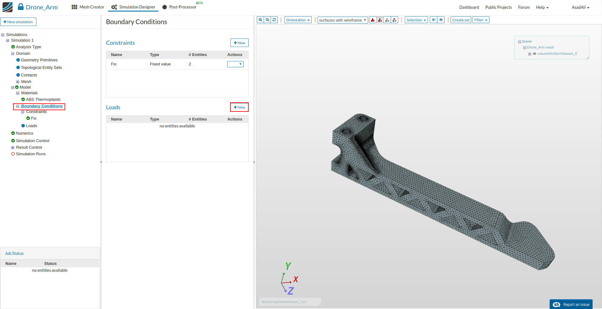
- Name: Lift
- Type: Force
- fy = 3
Finally assign this boundary condition to the top surface of the engine mount.
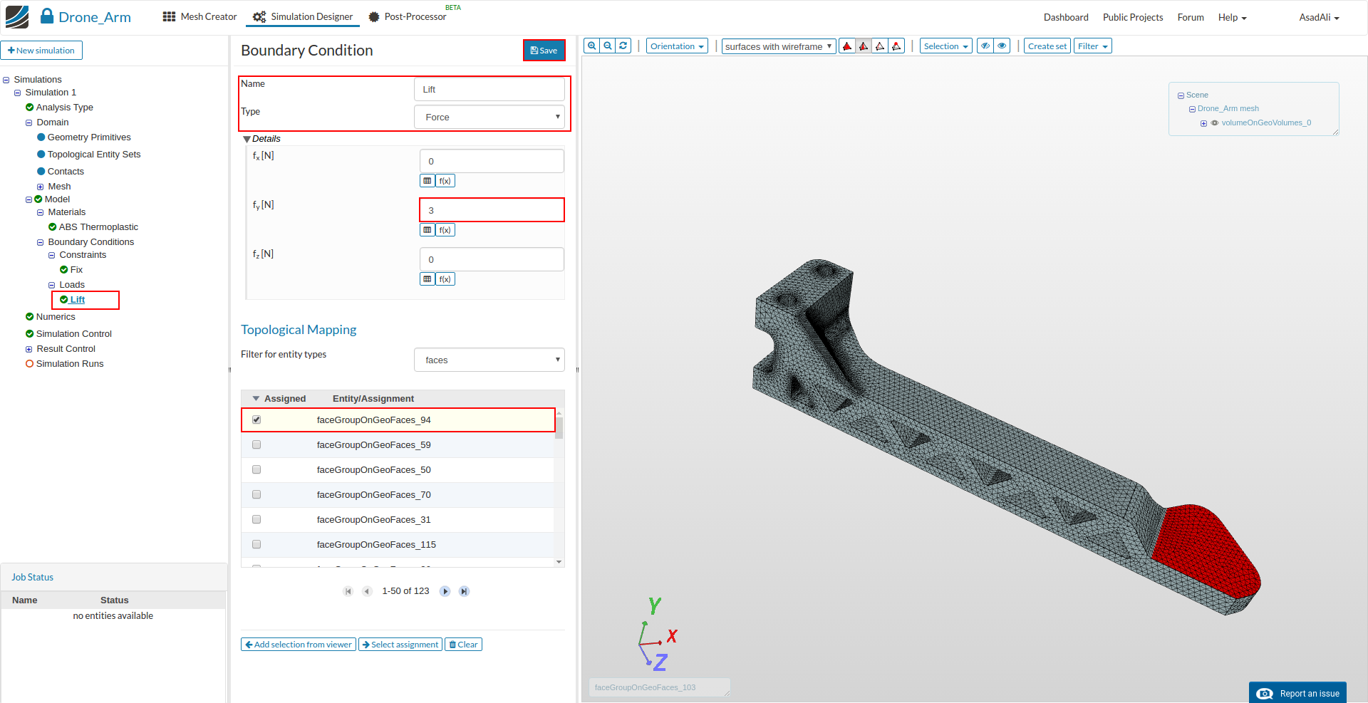
In this tutorial we want to investigate the deformation of the arm for different lit forces. Therefore you have later on to modify the value.
Numerics, which is the next item in the project tree, can be skipped since the default settings are fine.
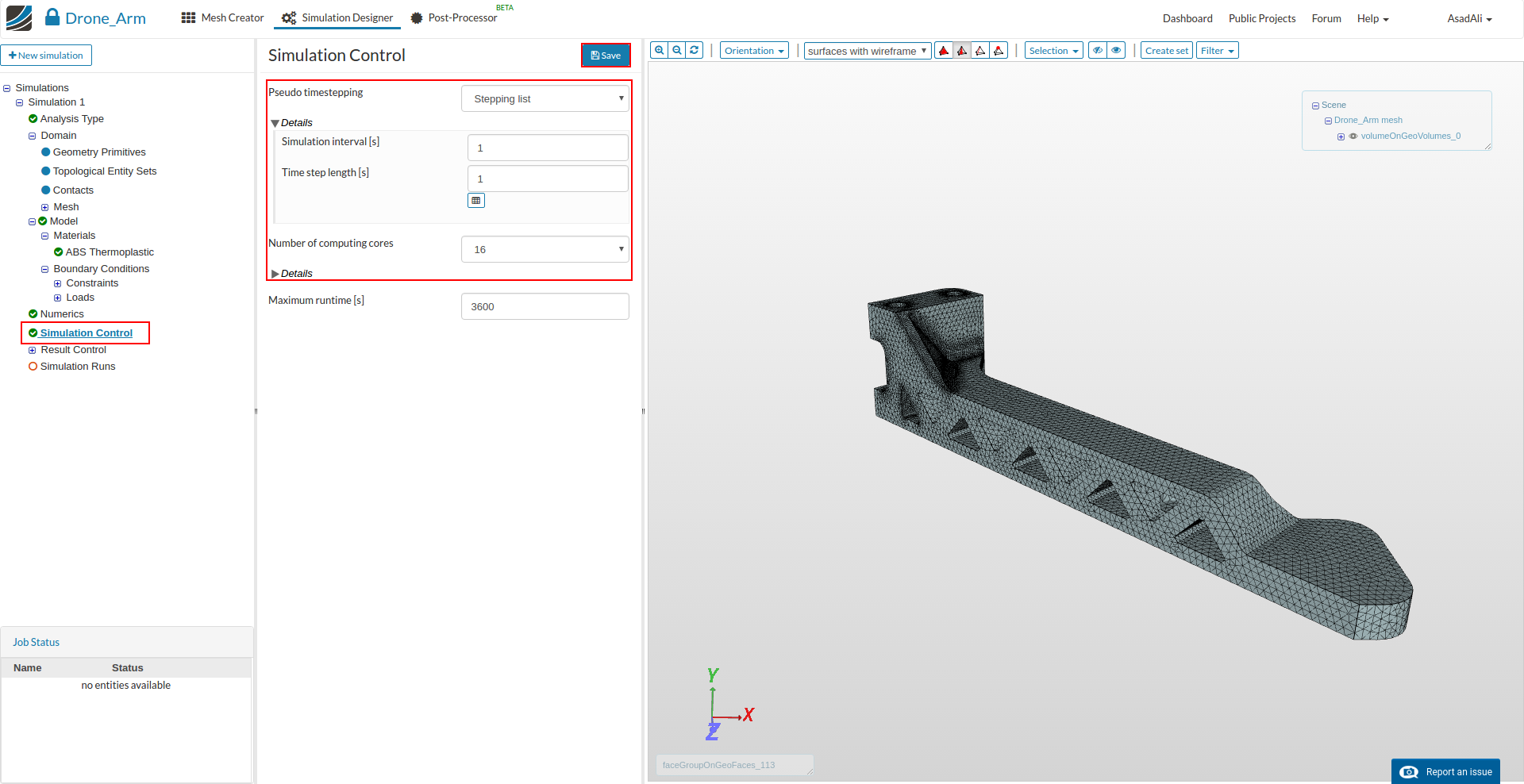
Click on the Simulation Control item in the project tree to specify how fast and accurate you want the simulation to be computed and change following values/settings:
- Timestep definition: Auto
- Simulation interval: 1
- Initial time step lengths: 1
- Number of computing cores: 16 (that will accelerate the computing process)
Please note that static linear simulations are not solved iteratively. The simulation time here is a kind of ‘pseudo-time’ which is for example used to modify the lift force based on the function we defined. The calculation will stop automatically when an aimed residual is reached.
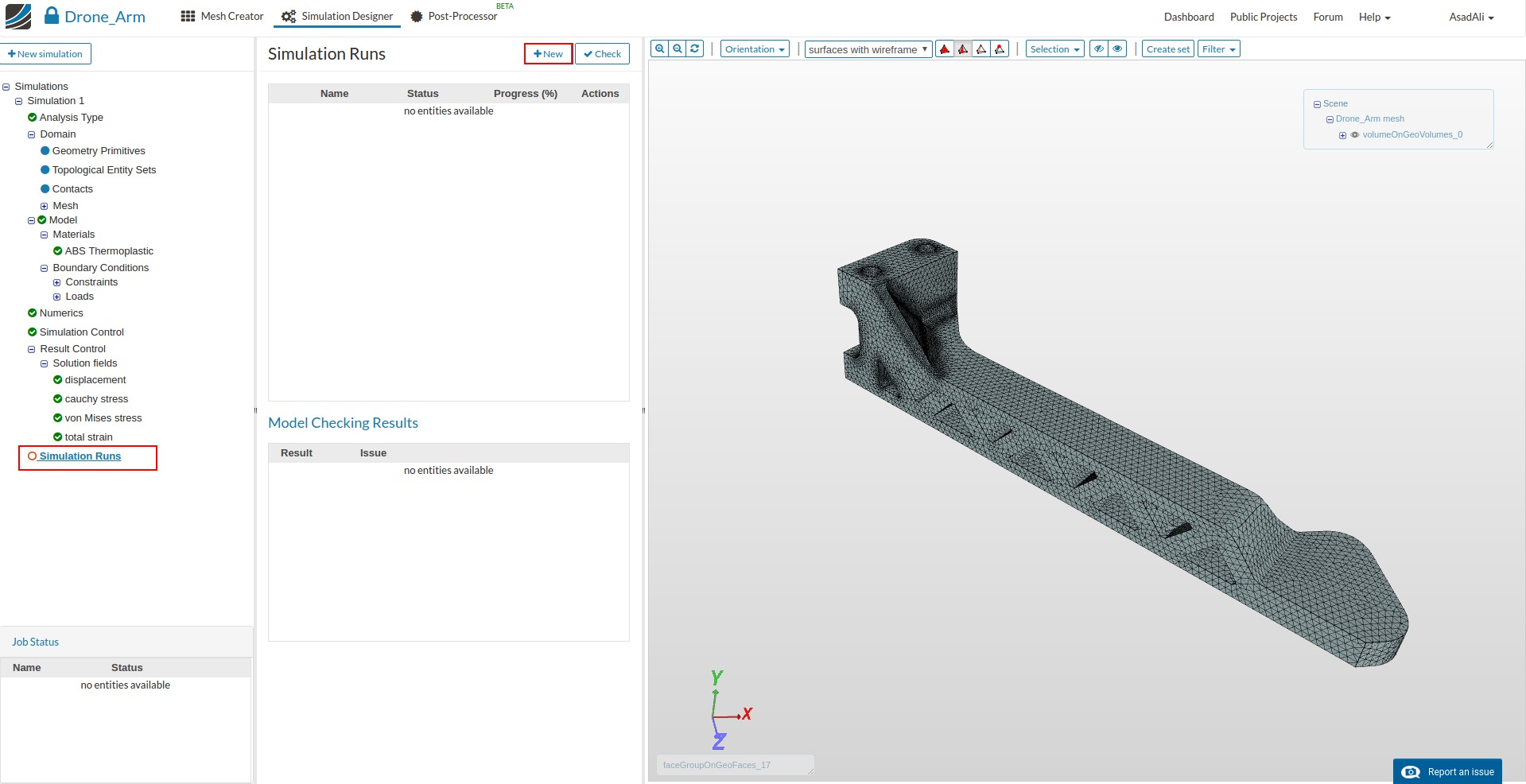
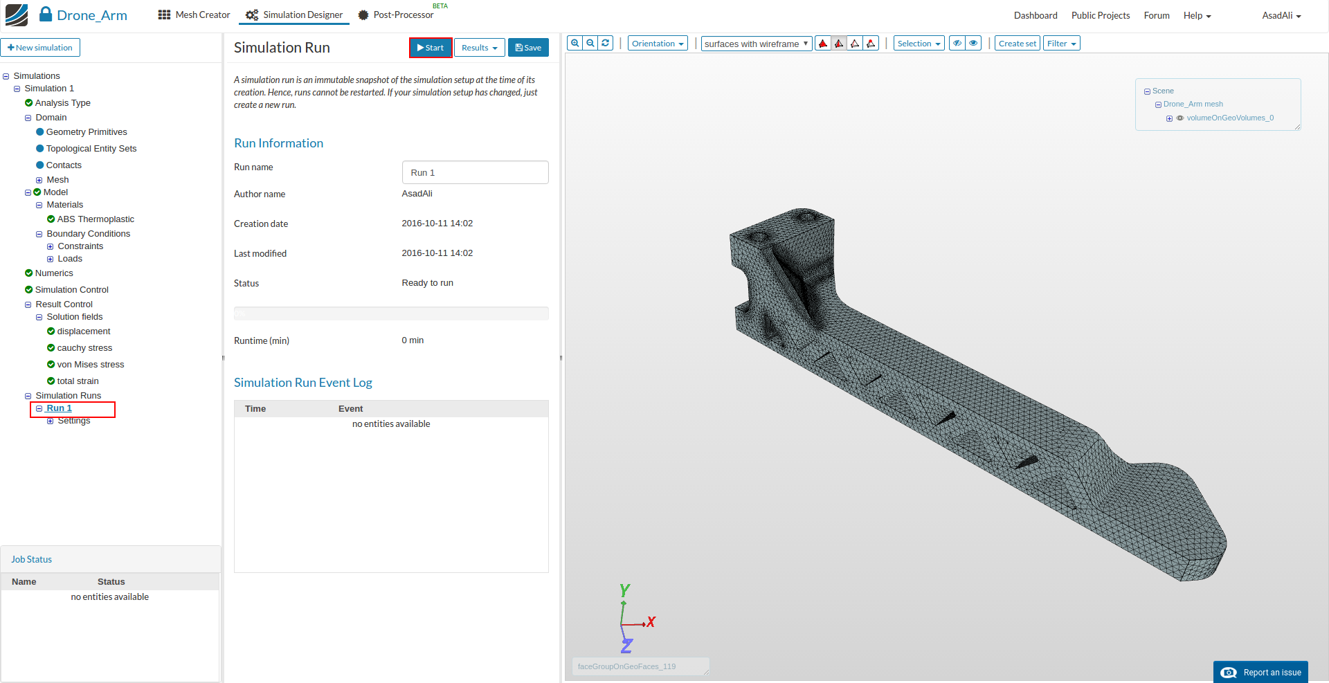
To start the simulation, click on the Simulation Run item in the tree and click on the Create new run button at the bottom of the middle column menu. This will create a snapshot of your simulation settings as a new sub-item.
You can now start the simulation run by selecting it from the project tree and then click on the Start button.
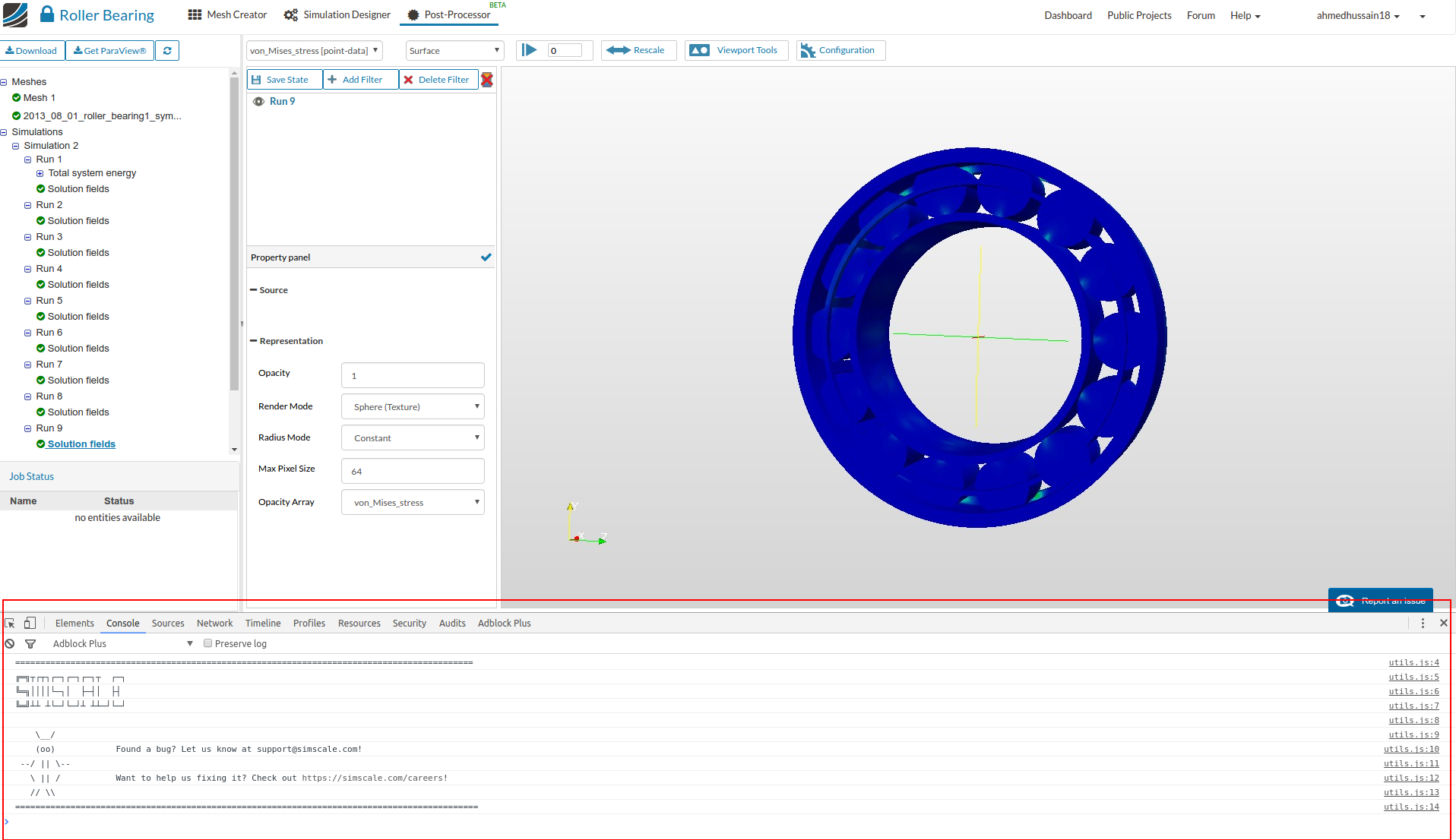
Post Processing
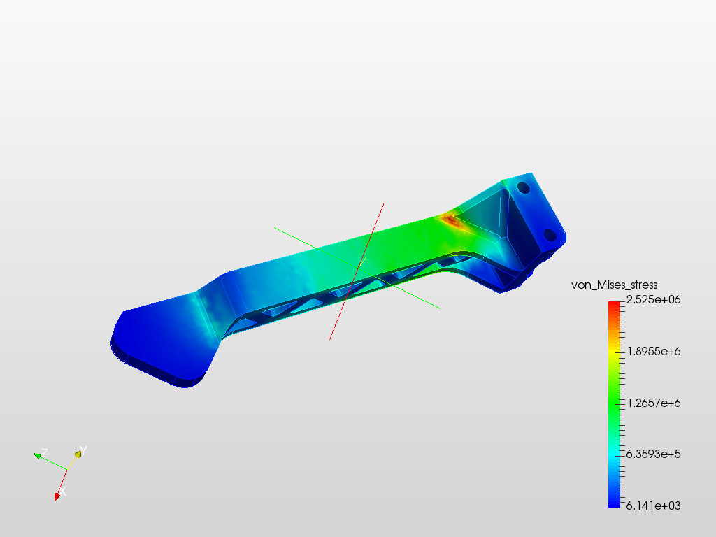
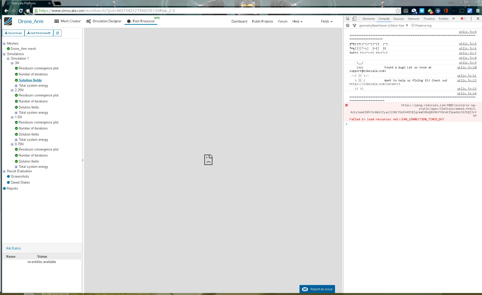
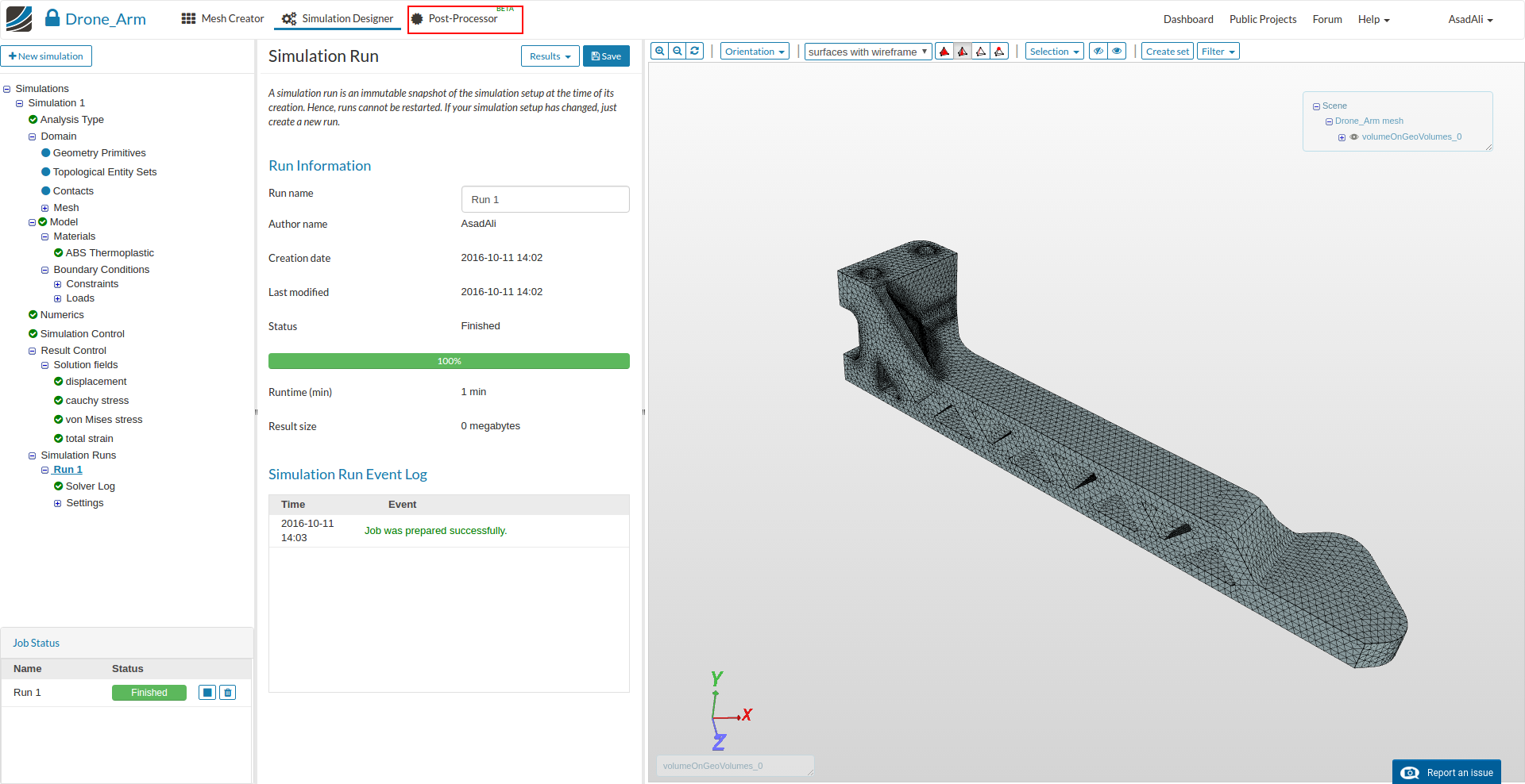
Move to the Post-Processor tab and click Click on the Solution fields in the project tree to access the 3D simulation results.
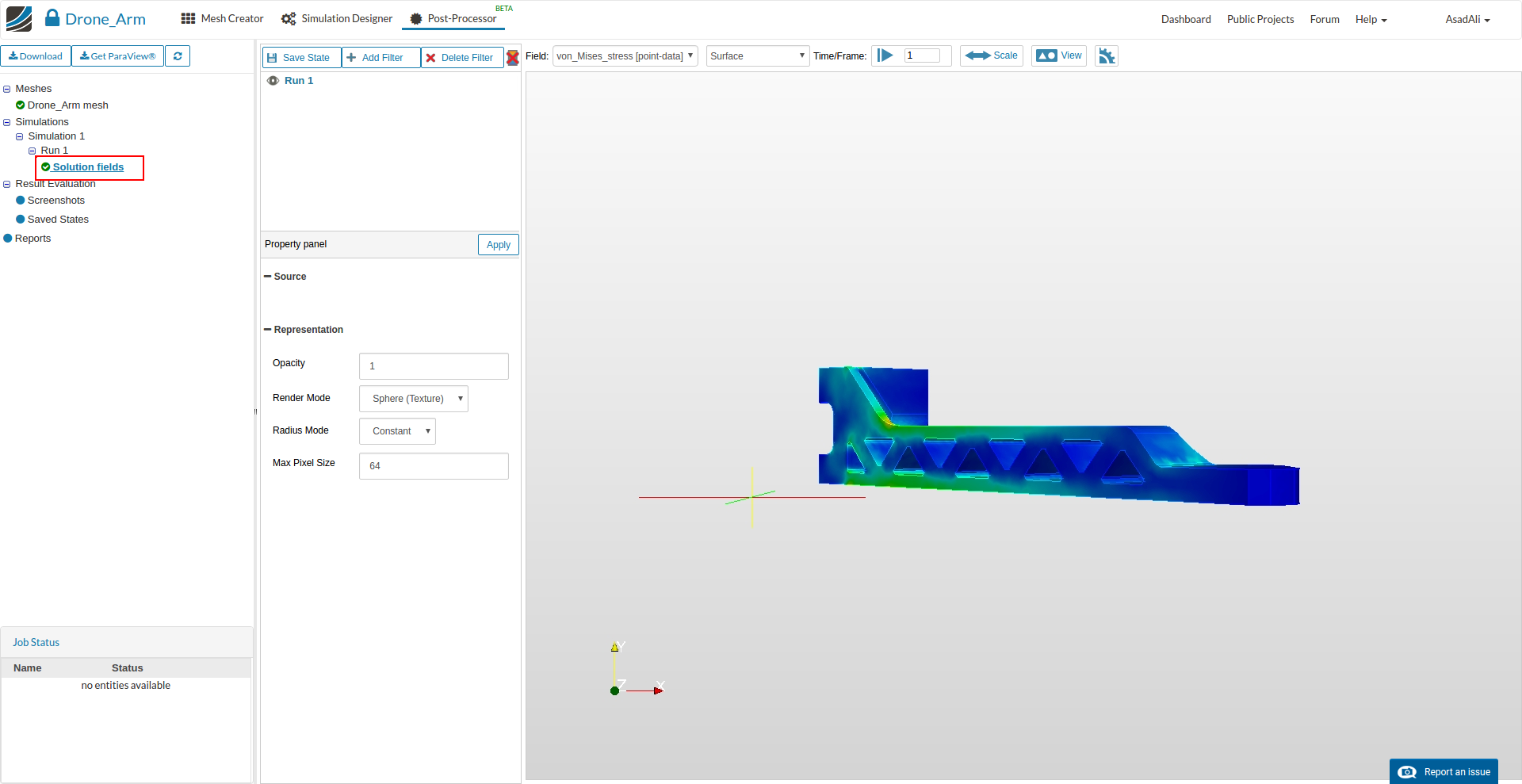
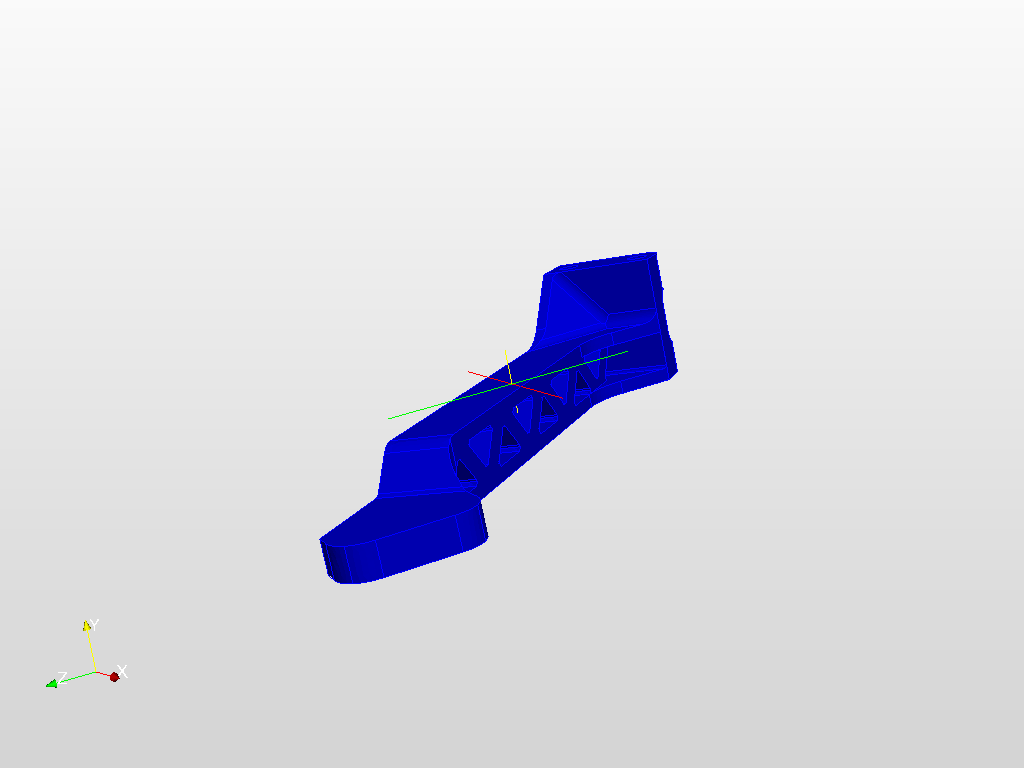
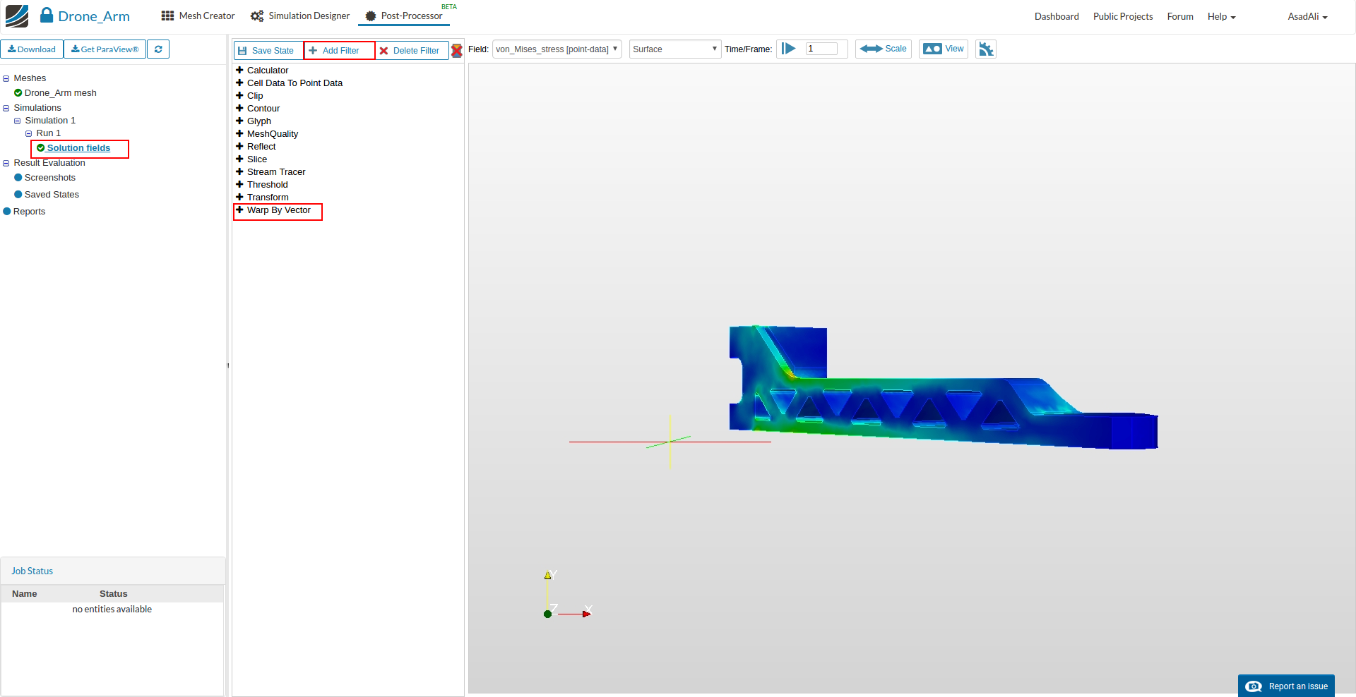
First we will visualize the deformation of the arm using the WarpbyVector filter.
Click therefore on the Add Filter button.
Now you can choose the WrapByVector filter from the list.
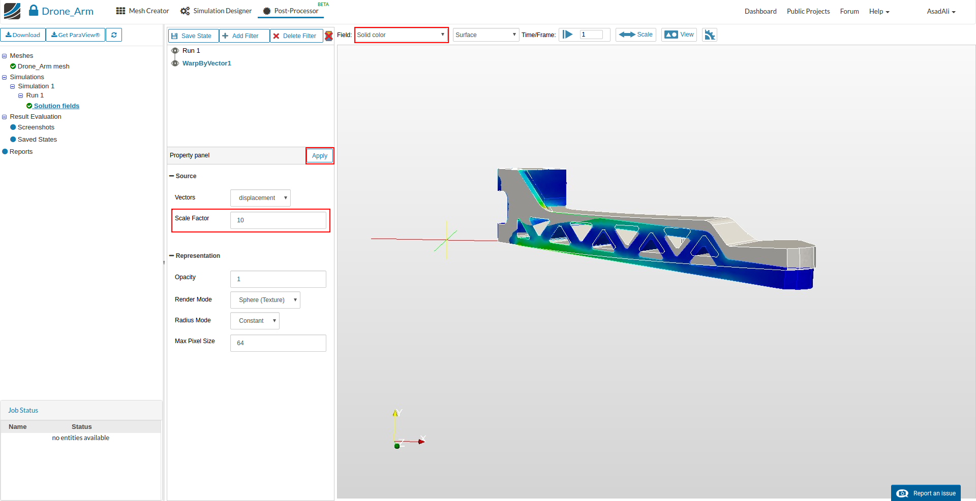
Next define a scale factor for the displacement. Choose a factor of 10 and pess Apply. Finally change the solution field to solid color.

 ?
?